Hello to everyone!
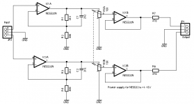
I have just built up a very simple headphone amp with two NE5532. It works very well and I just would like to know ,
if I've made some cardinal faults in the schem, for example if I did some "Don'ts" or forgot some "Do's".
Please have a look at the attached schem and tell me what You think about it.
A little problem I have is the popping sound in the headphone when I turn on or off the power supply - especially when the positive and negative supply voltages don't raise or fall exactly at the same time.
Does anyone know a good way to avoid this?
Any hints would be appreciated!
Attachments
Welcome to diyAudio 🙂
Things I notice would be:
1/ The 5532 is great opamp but one of the worst for having relatively high 'input bias currents'. This means that unless both inputs see the same impedance then you will have a small DC offset.
2/ DC coupling the volume control means the offset at the headphone will change as you alter the volume (because the DC resistance the input pin sees alters)
3/ DC coupling the volume control can cause crackling and noise, particularly as the pot wears a little.
4/ The input as drawn relies on the source having a nominal zero volts DC present. If that source is AC coupled then the opamp has no DC reference and over a short time the output will drift toward a rail as the cap in the source component charges.
So ideally you should AC couple the input and provide a suitable DC path to ground for the opamp input (say 100k).
The output of the first opamp should also be AC coupled to the pot.
The pot wiper should be AC coupled to the last opamp and again you need a DC path to ground (100k)
A 5532 will still give a small offset at the headphone output even when all this has been done because of the different impedances seen by both inputs. Adding a 100k between pins 6 and 7 would stop that but would not be my choice tbh. Perhaps a different opamp here like a 4562. Having said that the offset is small and any series resistor to the phones will reduce it further (at the phones)
The noise at power on and off is normal and the only way to get a truly silent on and off is to have a reliable mute circuit on the output. It is the same problem with power amps. That can be a simple circuit, particularly if it is mains powered.

Welcome to diyAudio badger 😀
Mooly is, as always, spot on with his observations.
Here are a couple of output mute / delay circuits for you to try:
https://www.diyaudio.com/community/...level-audio-output-delay-retrofit-pcb.358940/
https://theslowdiyer.wordpress.com/2018/04/30/project-files-simple-power-on-delay-with-555-ic/
Mooly is, as always, spot on with his observations.
Here are a couple of output mute / delay circuits for you to try:
https://www.diyaudio.com/community/...level-audio-output-delay-retrofit-pcb.358940/
https://theslowdiyer.wordpress.com/2018/04/30/project-files-simple-power-on-delay-with-555-ic/
A gain of 7.7 before the volume control may be excessive.
Coming from a 2V source (CD, DAC), the opamp wants to swing 21.6V peak, which it can not do on +/-15V supplies.
I'd drop the first stage, cap-couple into the volume pot, then take a gain of maybe 3 in the output stage.
(Actually my last HP amp, I started with a 0-10 variable-gain stage to cover a w-i-d-e range of signals in location recording and experimentation, but that would be overkill for pleasure listening.)
Honestly, I appreciate your answers
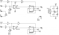
The use of a BUF634 might indeed be a good idea. I read the datasheet of the BUF634 and found a schematic for a HP amplifier using the BUF634.
The Volume control is done by a CS3310 in the stage before the signal reaches the inputs of the HP amp. So please tell me what You think of this (see attached schem).
Attachments
If he has headphones with less than 250 ohms impedance in series with the 470 ohms resistor it means that he needs at least three times more output swing.My 250 ohms headphones get max 3.75 volts rms , that means 11 v output swing needed at max power.11/2 =5.5 x gain so a gain of 6 is ok for 2V input with 470 ohms output resistor.He could drop that to 220 ohms with a reasonable load between 400...500 ohms including headphones so 32 ohms headphones could not be used safely.Paralleling two ne5532 or even 4 of them as in D.Self books woold be a better ideea.A gain of 7.7 before the volume control may be excessive.
Coming from a 2V source (CD, DAC), the opamp wants to swing 21.6V peak, which it can not do on +/-15V supplies.
I'd drop the first stage, cap-couple into the volume pot, then take a gain of maybe 3 in the output stage.
(Actually my last HP amp, I started with a 0-10 variable-gain stage to cover a w-i-d-e range of signals in location recording and experimentation, but that would be overkill for pleasure listening.)
Please answer lineup's questions. Headphone needs range ALL over the map.What are your headphones?
What is the impedance of your headphones?
Not going to calculate or speculate without a clear goal.If he has headphones with less than 250 ..470 .. 250.. 3.75 .. 11 ... 11/2 =5.5 .. 6 .. 2V .. 470 .. 220 .. 400...500 .. 32 ..ne5532
True...but I have 2 × AKG 200/600 ohms, two Sennheisers 64/600 ohms, Bayerdynamic 250 ohms , a few Sony and Philips 32 ohms , Stanton 64 ohms...my headphones are all over the map too so I wouldn't be able to have a universal headphones amp based on 1/2 ne5532..Please answer lineup's questions. Headphone needs range ALL over the map.
Not going to calculate or speculate without a clear goal.
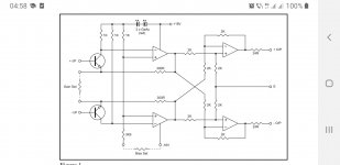
We could also derive a capable 300 ohms loaded ne5532 balanced input and output headphones amp from Grame Cohen's mic preamp by droping the input trz and the output stage if we had balanced signal input and balanced headphones plugs 🙂
Attachments
So go ahead and design a DIYAudio Reference Headphone Amp, and explain the design choices as simple as possible.We could also derive a capable
I don't believe in refference headphones amplifiers nor I dare taking their self made designers seriously...mostly because i cloned a lot of good commercial designs an designed some others in all technologies except fully discreet transistors. Even for fully discreet transistors I'd give Tandberg 3014 second edition clone a try before getting too "original".
I'd choose a 30...40 years old commercial design anytime over any of the today's solid state hyped audiophile versions.Just a few weeks ago I recapped an old Telefunken cassette player in which I also changed the njm4558 with opa2132 op amps.I wonder what would the "refference guy say" about me being thrilled by this cassette deck driving my headphones through 22uF caps.
I can tell though that its base signature was so damn good on 250 ohms Bayerdynamic that I simply couldn't believe.Have to try 600 ohms AKG on it one day.
By the way , my tpa6120 is only accumulating dust for about two years cause I found my class d chip inside phone and laptop good enough.I bought some class t ta2024 kits only to give Topping tp 31 ideea a try.
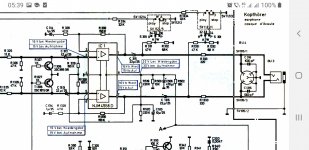
Here's your 4x op amp headphones amp with 220 ohms ouyput resistors supplied with 24 V dc from 1980:
I'd choose a 30...40 years old commercial design anytime over any of the today's solid state hyped audiophile versions.Just a few weeks ago I recapped an old Telefunken cassette player in which I also changed the njm4558 with opa2132 op amps.I wonder what would the "refference guy say" about me being thrilled by this cassette deck driving my headphones through 22uF caps.
I can tell though that its base signature was so damn good on 250 ohms Bayerdynamic that I simply couldn't believe.Have to try 600 ohms AKG on it one day.
By the way , my tpa6120 is only accumulating dust for about two years cause I found my class d chip inside phone and laptop good enough.I bought some class t ta2024 kits only to give Topping tp 31 ideea a try.
Here's your 4x op amp headphones amp with 220 ohms ouyput resistors supplied with 24 V dc from 1980:
Attachments
Last edited:
Sorry to see he didn't answer my question.
What impedance are your headphones?
What is the model?
To ccover all impedances, I need at least 2 different headphones amplifiers.
One for lower impdances deliver mostly currents.
One for higher impedances deliver mostly voltages.
What impedance are your headphones?
What is the model?
To ccover all impedances, I need at least 2 different headphones amplifiers.
One for lower impdances deliver mostly currents.
One for higher impedances deliver mostly voltages.
Absolutely! It's basic Studer design and it works pretty well even when used in class B .Also my first headphones amp I built back in 2013.Here's a simple one that will get the job done: https://sound-au.com/project113.htm
Last edited:
Simpler version based on njm4556 that sound really well would be Nakamichi CR4 and Yamaha kx 990 , with Technics SL-P990 being the best version with njm4556 that exhibits same order of distortions as tpa6120.
Here's a simple one that will get the job done: https://sound-au.com/project113.htm
What opamp did you use in that circuit?Absolutely! It's basic Studer design and it works pretty well even when used in class B .Also my first headphones amp I built back in 2013.
I would go for OPA2134.
- Home
- Amplifiers
- Headphone Systems
- Headphones