Very cool! Thanks for that Arduino link. Never saw that before.
You connected line power safety earth to chassis, so for life protection it's OK.
<<
phew!
IMHO the long ground wire, where components grounding has random connection points, not optimal.
Sooner I will draw sample grounding scheme.
<<
Many thanks in advance 🙏
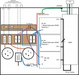
See attached for an abbreviated version of my current wiring scheme. I know the input should be closest to the chassis connection. I tried it that way too, but no difference, so went with the more convenient visually cleaner layout. But I can still try some variations.
BTW are you tried four wire (+Out, +S, -Out, -S) method?
Remote sensing on the load (for example preamp channel B+ tied to +Out, +S, and preamp channel GND to -Out, -S) gives better regulation.
<<
Yes, currently I am using 4 wire w remote sense connection
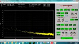
-78dB hum component not too bad, but if you look carefully it's interfering with 1kHz signal, and make +/- 60Hz sidebands (modulation) at -103dB.
<<
Yes, I see that. Yeah, getting it down to -90dB would be a noble goal. Maybe I can get there.
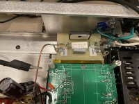
Are you sure, that switching PSUs metal part not connected to case? I saw there metal threaded rods.
<<
Thanks for taking such a careful look. Yes the PSU's metal part is connected to chassis via the 4 machine screws. I would assume that that should still be ok. I can check to make sure the output is indeed floating. Otherwise it should be ok that the PSU metal is in contact, I would think. Do you think that the PSU metal should not be in contact at all, even if the outputs are indeed floating?
You connected line power safety earth to chassis, so for life protection it's OK.
<<
phew!
IMHO the long ground wire, where components grounding has random connection points, not optimal.
Sooner I will draw sample grounding scheme.
<<
Many thanks in advance 🙏
See attached for an abbreviated version of my current wiring scheme. I know the input should be closest to the chassis connection. I tried it that way too, but no difference, so went with the more convenient visually cleaner layout. But I can still try some variations.
BTW are you tried four wire (+Out, +S, -Out, -S) method?
Remote sensing on the load (for example preamp channel B+ tied to +Out, +S, and preamp channel GND to -Out, -S) gives better regulation.
<<
Yes, currently I am using 4 wire w remote sense connection
-78dB hum component not too bad, but if you look carefully it's interfering with 1kHz signal, and make +/- 60Hz sidebands (modulation) at -103dB.
<<
Yes, I see that. Yeah, getting it down to -90dB would be a noble goal. Maybe I can get there.
Are you sure, that switching PSUs metal part not connected to case? I saw there metal threaded rods.
<<
Thanks for taking such a careful look. Yes the PSU's metal part is connected to chassis via the 4 machine screws. I would assume that that should still be ok. I can check to make sure the output is indeed floating. Otherwise it should be ok that the PSU metal is in contact, I would think. Do you think that the PSU metal should not be in contact at all, even if the outputs are indeed floating?
Attachments
Sample grounding schema.

Use it individually for both channels, and then the channels (only one) common point would be the (common) HV PSU "cold" point.
Place the input (R1) and output (R4) "load" resistors as close as possible to the connectors and to the tube.
Use it individually for both channels, and then the channels (only one) common point would be the (common) HV PSU "cold" point.
Place the input (R1) and output (R4) "load" resistors as close as possible to the connectors and to the tube.
Last edited:
That can be a forever project. In my old kitchen all outlets tested "bad". But first: no single breaker turned off the outlets. TWO breakers fed two lines cross-connected behind the sink. With the lines dead: all but one were open ground. There were green/bare wires in the wall but they had cut them off. I managed to jiggle enough cable into each box to splice the greens together. Now fully 60% of the outlets showed H/N reverse.I have a new found interest to check all the receptacles in my house now.
That house still had knob-and-tube in the eaves but I did not find any in use. (I found much worse stuff...)
Ok thank you for this. You basically have a true single point star. I will do some rearranging and report back.
i guess I got the idea from Ale Moglia where he said to separate the Coleman 0V point from the input and output points and he uses 3 local stars. But who knows I still get very confused by this.
The most important part of the build work is grounding and avoiding ground loops. A combination of star grounding is recommended. I do the following star ground combination:
i guess I got the idea from Ale Moglia where he said to separate the Coleman 0V point from the input and output points and he uses 3 local stars. But who knows I still get very confused by this.
http://www.bartola.co.uk/valves/2013/10/28/2663/
The most important part of the build work is grounding and avoiding ground loops. A combination of star grounding is recommended. I do the following star ground combination:
- Input stage
- Filament bias return
- Output stage
That can be a forever project. In my old kitchen all outlets tested "bad". But first: no single breaker turned off the outlets. TWO breakers fed two lines cross-connected behind the sink. With the lines dead: all but one were open ground. There were green/bare wires in the wall but they had cut them off. I managed to jiggle enough cable into each box to splice the greens together. Now fully 60% of the outlets showed H/N reverse.
That house still had knob-and-tube in the eaves but I did not find any in use. (I found much worse stuff...)
Hah yes, that sounds like it might be the case for me too. The house is from 1925. The kitchen is new, and there was a stack of receptacles that were run to all the floors in a vertical row probably in the 80's or 90's for air conditioners, so I presume those outlets are good, although I will have to test. All the others are going to be a giant 'who knows'. I live in Brooklyn, and interestingly all the wiring, even the old is armored cable. It's the current code too I believe (an NYC electrician may be able to correct me)
Some may have been on Edison's original DC system, common in the downtown section of NYC at that time.Hah yes, that sounds like it might be the case for me too. The house is from 1925. The kitchen is new, and there was a stack of receptacles that were run to all the floors in a vertical row probably in the 80's or 90's for air conditioners, so I presume those outlets are good, although I will have to test. All the others are going to be a giant 'who knows'. I live in Brooklyn, and interestingly all the wiring, even the old is armored cable. It's the current code too I believe (an NYC electrician may be able to correct me)
In the lab I worked in at U of T Physics in downtown Toronto the building wiring still existed for an olde DC supply.
The large fan that ventlated the theater at one time ran on DC, it was not removed until much later because of its size.
And two others, 25 & 60 Hz. Southern Ontario & I think parts of western NY state were still on 25 Hz until as late as 1950.
And all the lights flickered. The 25 Hz system system still ran for industrial accounts in the Niagara area, electric steel furnaces
& manufacture of Cyanamide.🙂
Soon after the first electric fires, Boston NYC and other dense cities mandated all-pipes wiring. Later changed to conduit and then armored cable. Last I knew, NYC had not relaxed from metal-enclosed wiring.all the wiring, even the old is armored cable
Mine was a century older, though that hardly matters for the electric, which probably did not come out to the farm until the 1920s. Matters because there was no common lumber in the place, all adzed trees. Fun to run wires through.The house is from 1925
Interesting history as to house wiring. Yes, that's correct, armored cable is still mandated here.
Some big progress.
So, Bela I added the loop breaker after all. I gained a 2dB or so. Thanks!
But the big news is that adding grounded aluminum foil that you mentioned got the noise down another 7-10dB more, so now we got to -90dBV. Quite an accomplishment I feel. Thanks for prodding.
FFT with the 60Hz hump is loop breaker w no foil. The flatter one is with aluminum foil.
Interesting also is that when I start up the tube, for the first 10m THD is at about -75dBV. After an hour it creeps down to -90. Interesting, and pretty swell!
Also, on the loopbreaker, the standoffs are plastic. Before anyone asks 🙂
Kind of dissapointed that I may have to shield these guys!
Attachments


Last edited:
GOAT made zillions of nice tube shields but most have been discarded? Here's one on Esty.dissapointed that I may have to shield these guys!
Last edited:
Read #300 post here:Kind of dissapointed that I may have to shield these guys!
https://www.diyaudio.com/community/...-el84-6v6-or-el34.366110/page-15#post-6603892
indeed very interesting. In the one FFT without the aluminum foil, noise even looks not so bad at -80dB. But if I take that amp and move it 10 ft (with an extension cord, still connected to my properly grounded receptacle) noise goes up 20dB to -60db at 60hz. With shielding it’s pretty stable at -90 no matter where in the room I move. So problem kind of solved I guess.
Will have to keep on the lookout for some nice looking shields. I ordered a few more tubes so we’ll see with that.
i guess there are some drawbacks to going down the road of using 100 year old tubes. Amazing they even work!
So, I had an interesting session tonight. I brought the 71 into a bedroom and listened to it.
I currently have this setup:
Laptop (always plugged into the wall) --> USB DAC --> Salas 6V6 preamp --> Hypex Ncore module (15dB gain) --> Troels Bookshelf
To me, it sounds pretty good! The 6V6 is traditional power supply, Maida etc. DC heaters. I spent a lot of time getting the thing quiet and finally got there.
Anyway, I kept everything the same, and just swapped out the 6V6 for the 71a (with aluminum foil shield of course!). Sounded nice tonally, but noisy as hell. Some 60Hz in there but a lot of buzzing through the entire spectrum. Decided to make one change-- I just unplugged the AC/DC brick from the laptop and let it run on battery. Now, almost total black silence. I could hear some 60Hz only if I put my ear in the woofer practically touching the cone, and I could hear a bit of hiss through the tweeter at up to 3-4 inches, but beyond that very quiet and far above acceptable.
And turned on some tunes. Wow, I really really like what I hear. Sounds to me cleaner than the 6V6 (confirmation bias I know), but sounded really nice. Dare I say spooky (probably more confirmation bias + cliche), but still... did I say I like it?! Seriously, what a fun project.
So this grounding thing is getting to me. How come I have exactly zero problems with plugged in laptop + USB Dac with the 6V6, but with the 71a it's a buzzfest? Only quiet with laptop on battery.
Anyway, I ordered a few more tubes from ebay, so I can try some more in a few days time.

I see in the article that he is suggesting cutting the connection between V- and earth on the B+ and filament supplies.
I'm not using 2 supplies, rather 1, and then they split to 2 isolated DC DC converters.
Or are you referring to me cutting the connection between earth and V- on the laptop brick from Lenovo? Btw the laptop supply has a 2-prong AC plug.
Could you clarify?
I'm not using 2 supplies, rather 1, and then they split to 2 isolated DC DC converters.
Or are you referring to me cutting the connection between earth and V- on the laptop brick from Lenovo? Btw the laptop supply has a 2-prong AC plug.
Could you clarify?
The laptop PSU hasn't connection between V- and safety earth, even if the later is available.
As I suggest, must to clarify that AC-DC converter working such mode, or not.
If the DC-DC converter -In not isolated from -Out, using tow of them from one raw DC also would generate ground loop.
As I suggest, must to clarify that AC-DC converter working such mode, or not.
If the DC-DC converter -In not isolated from -Out, using tow of them from one raw DC also would generate ground loop.
Ok, thanks for this. Yes it must be something related to all this as you say.The laptop PSU hasn't connection between V- and safety earth, even if the later is available.
As I suggest, must to clarify that AC-DC converter working such mode, or not.
If the DC-DC converter -In not isolated from -Out, using tow of them from one raw DC also would generate ground loop.
I will double check again the laptop supply. With a 2 prong cord, there is no opportunity for V- to connect to earth, isn't that correct?
With respect to the DC conversion, the main AC/DC SMPS is a Vicor Flatpac. I tested V- to earth ground/chassis this morning for continuity, and they are not connected.
Also, the DC DC converters -In to -Out is indeed isolated. Let me check again when I get home later.
What comes to mind though, is that Vicor recommends that the DC DC converters are bypassed to their baseplates, which are connected to the chassis. But this is through a .01uF and 4700nF Y-cap, and I have implemented that in the PCB I made. See here for the design guide page describing that.
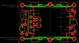
Also, see attached PDF for my schematic that I used for the PCB that I made as a shield for the DC DC converters. Attached is the one for the B+. I used 3 stacked, as described in the attached application note AN1, but the filament converters use the same pcb as well in conjunction with a ripple attenuator module. W5 and W6 on my pcb schematic are wire pads/holes that I used as a through hole for a screw which connects to a metal standoff which is connected to chassis. Attached is a screen shot of my PCB. I actually made a bunch of mistakes on it, argh! (too small of holes) and some placement errors which I corrected manually by grinding a few traces away, and drilling out. Not perfect, but works. Electrically fine though. No claims to being a PCB expert!
If the Y-cap from in and out to chassis of the DC converters is the issue, that I may have a fatal flaw.
Interesting though, the distortion analyzer I am using is a Quantasylum QA400, data sheet here, which is an old unit, single ended, and requiring max Windows 7. The unit I believe is NOT isolated, so I'm surprised all this noise isn't showing up there, which is connected to a (different) laptop. Maybe that one has a third prong AC connection I have to check.
Attachments
Sorry, but pictures in #13 post only two wire (red, black) goes from SPMS Out to preamp stage.BTW are you tried four wire (+Out, +S, -Out, -S) method?
Remote sensing on the load (for example preamp channel B+ tied to +Out, +S, and preamp channel GND to -Out, -S) gives better regulation.
<<
Yes, currently I am using 4 wire w remote sense connection
The sense pins of SMPS output directly connected to +Out and -Out.
It's working, but four wire options (+Out and +S connected together at B+ point, -Out and -S on Gnd) is better.
https://www.tmatlantic.com/encyclopedia/index.php?ELEMENT_ID=22008
Ah ok, sorry there is some confusion. I implemented Sense on the output of each converter. The B+ is made up of a stack of 3 converters, each trimmed to about 70V. And so sense is tied to + and - at each module as per this application note. There's another note about how to implement trim with all of this which I can't find right now, but it's basically the same with the addition of a trim resistor. Each module in this stack is 24V In/ 95V out. Output is trimmable to 50%.
- Home
- Amplifiers
- Tubes / Valves
- 71A preamp