I still have to figure out this ground loop thing when connecting to outside equipment. Not that I want to (need to figure out the cause), but would an input transformer cure the situation? Maybe something from Llundahl or Jensen
Well, this is quite interesting. I just bought some new, ancient tubes on ebay.
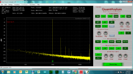
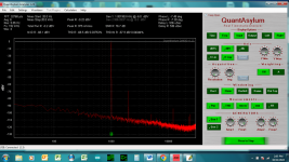
Listened to them and thought, wow this seems louder than the old set. Put it on the analyzer.
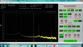
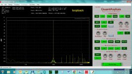
Not sure what that peak is at 11K. Some kind of oscillation? Input goes straight to a stepped attenuator and then the tube. Attenuating all the way down to min volume doesn't change that peak, nor does changing the frequency. It's there a tiny bit even with loopback with the amp off and disconnected so maybe the tube is picking up something in the room.
Should I use grid stoppers btw?
Also would an input transformer solve my ground problem when connecting to an external dac? Still perplexing my why the analyzer which is not isolated not exhibiting the noise like the dac makes when connected.
Thanks for watching my little experiments!
Listened to them and thought, wow this seems louder than the old set. Put it on the analyzer.
- Noise floor is much lower (still need to shield the tubes w foil though).
- Gain is much higher (6.5 dB vs 3dB before)
- Distortion is higher. H2 now in the -60's rather than -80 before)
Not sure what that peak is at 11K. Some kind of oscillation? Input goes straight to a stepped attenuator and then the tube. Attenuating all the way down to min volume doesn't change that peak, nor does changing the frequency. It's there a tiny bit even with loopback with the amp off and disconnected so maybe the tube is picking up something in the room.
Should I use grid stoppers btw?
Also would an input transformer solve my ground problem when connecting to an external dac? Still perplexing my why the analyzer which is not isolated not exhibiting the noise like the dac makes when connected.
Thanks for watching my little experiments!
Attachments

Last edited:
I can't quite figure out this ground loop issue, and anyway I have a balanced dac so was thinking to try some input transformers. If I have some Altec 15335A 15K:15K transformers, can I use them at the input of this preamp?
Right now I have a 100K stepped attenuator at this input, so I should parallel an 18K with a attenuator and that should be ok? Or maybe just remove the attenuator for now if it complicates things?
I've read the cinemag and jensen application notes, and in some cases I see a an RC in series at the input or output.
I'm a bit confused so if someone can give me an easy answer I would greatly appreciate it.
- Is a15K from grid to ground at the input ok for this preamp? I'm not sure it if has any bandwidth implications
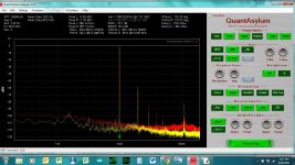
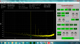
Some updates! I bought some Cinemag input transformers and it completely obliterated any brood spectrum noise I was experiencing.
I also added a little more filtering on the B+ and filament supplies, and I think I landed at a pretty good spot. Sounds really great- I’m enjoying so far.
Only issue is there is some high frequency garbage at 11k and 22k. I might try to tackle that another time. For now at least I’m satisfied. I’m using 3 dc dc converters in series to create the B+ and then 2 more for each of the filaments, so I’m pretty sure I’m getting difference tones. Anyway though it’s pretty quiet!
Other problem is matching tubes which I know is impossible. I might add a compensation pot somewhere later. Right now the two tubes I have are off by 2-3 db. Will tackle that another time.
Attachments
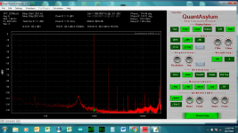

Some more updates- I think I'm pretty much there now:
- Changed from anode resistor to 10m45s CCS, a ala tubelab. 22ma. The variation in tubes was too much with the resistor. Some tubes 3dB different! with CCS, now between .5 - 1dB max. Sound is really nice! I prefer over the resistor load. More gain too
- Lowered B+ from 210 to 175V. Anode V is now around 120V or so
- Added ON-Delay module to delay B+ by 60s. I was finding that with CCS, the anode voltage would jump up almost to B+ while the tubes heated up.
- Added additional filtering on the filament supply.
- Added input filtering to the DCDC modules (.33R on VIN, and 100uF). That helped with the bit of noise at 12kHz. I think they are beat frequencies. Can't quite get rid of it entirely though. Slight fly in the ointment, but can barely distinguish a tone with my ear on the tweeter.
Attachments
Last edited: