What is that V2 in your lower circuit? If that is an external source, with a negative voltage with respect to ground, you can. If V2 represents the 86V point in the top circuit, it won't work create a neg voltage wrt ground.
Jan
Jan
What you want to achieve is not crystal-clear, to be euphemistic.
Would you like to ues the reference voltage as an auxiliary supply, with an inverted polarity?
BTW, I see no R5 on your schematic
Would you like to ues the reference voltage as an auxiliary supply, with an inverted polarity?
BTW, I see no R5 on your schematic
The first schematic is very confusing with the ground point after the pos rectifier but wanting a neg voltage and two series pass devices.
Why all the complexity? Just use a schematic you would normally use for a pos voltage, but reverse the rectifier (and change the pass device of course).
Reversed diode and grounding the bottom of the capacitor as you would normally do. Then you have a neg voltage wrt ground, and then put the source follower after it, similarly to the 2nd schematic.
Jan
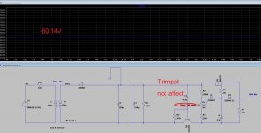
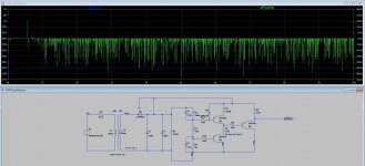
Did not work. a lot of noise. failed but another one work no noise (but fixed at - 60VDC can not adjust voltage)The first schematic is very confusing with the ground point after the pos rectifier but wanting a neg voltage and two series pass devices.
Why all the complexity? Just use a schematic you would normally use for a pos voltage, but reverse the rectifier (and change the pass device of course).
Reversed diode and grounding the bottom of the capacitor as you would normally do. Then you have a neg voltage wrt ground, and then put the source follower after it, similarly to the 2nd schematic.
Jan
Attachments
Last edited:
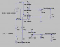
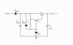
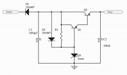
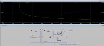
It can be simpler than that: a capacitive supply designed for a few mA/100V, feeding a simplistic adjustable regulator of your choice.
Dimension C1 according to the required current, typically 200 or 300nF:

Dimension C1 according to the required current, typically 200 or 300nF:
Oh!!! Thank you do much, mr. Dug. I am old and not smart. Sorry for many posts that seems annoy someone. I did not intend to do. I just really don't knowThis?
Ignore my post #27
Thank you very much i will try to draw in LTSPICE again today. My eyes sore from sitting too long with LTSPICE and still got no resultIt can be simpler than that: a capacitive supply designed for a few mA/100V, feeding a simplistic adjustable regulator of your choice.
Dimension C1 according to the required current, typically 200 or 300nF:
View attachment 1082972
simple Fixed bias scheme might better. adjust using zener diode (not effective but small board)
If anyone can adjust voltage please recommend Thank you.
If anyone can adjust voltage please recommend Thank you.
Attachments
Last edited:
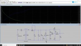
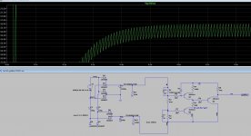
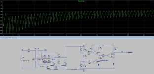
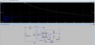
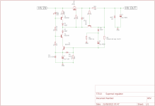
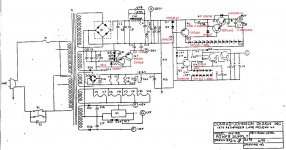
I couldnt sleep very well, so i breadboarded a regulator for the HV for you. My main problem with your regulator was two things:
A mosfet leaks slightly from gate to source, say .5mA to account for this you need a relatively low value of resistance from B+ to gate, by using a 2mA current source this is taken care of and the current source will work down to about 5V
secondly one wants to keep the dissipation out of the driver transistor this is better for voltage stability, i did this by building a cascode out of a high gain BC547 and a MJE340.
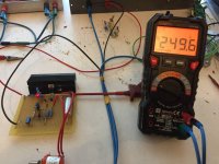
Attached the schematic, and a picture of the breadboarded regulator, with resistor instead of current source(I ran out of MJE350)
Cheers,
V4LVE
A mosfet leaks slightly from gate to source, say .5mA to account for this you need a relatively low value of resistance from B+ to gate, by using a 2mA current source this is taken care of and the current source will work down to about 5V
secondly one wants to keep the dissipation out of the driver transistor this is better for voltage stability, i did this by building a cascode out of a high gain BC547 and a MJE340.
Attached the schematic, and a picture of the breadboarded regulator, with resistor instead of current source(I ran out of MJE350)
Cheers,
V4LVE
Attachments

Have you seen the Pmillet shunt bias regulator? Its got what you need in terms of adjust-ability and is thoroughly tested.simple Fixed bias scheme might better. adjust using zener diode (not effective but small board)
If anyone can adjust voltage please recommend Thank you.
http://www.pmillett.com/bias_supply.html
Oh thank you very much. Politely bow to your help. I will try to simulate yours in LTspice againI couldnt sleep very well, so i breadboarded a regulator for the HV for you. My main problem with your regulator was two things:
A mosfet leaks slightly from gate to source, say .5mA to account for this you need a relatively low value of resistance from B+ to gate, by using a 2mA current source this is taken care of and the current source will work down to about 5V
secondly one wants to keep the dissipation out of the driver transistor this is better for voltage stability, i did this by building a cascode out of a high gain BC547 and a MJE340.
Attached the schematic, and a picture of the breadboarded regulator, with resistor instead of current source(I ran out of MJE350)
Cheers,
V4LVE
Yes, i am big fan of him. However i have try simulate his schematic in LTSPICE but failed. I am also big fan of T-Reg v.5 high voltage but when I try simulate. It failed. I can do simple LTspice (basic knowledge) hence difficult schematic, I failed. I will try again but my eyes sore with 4 hrs of LTSPICE. I might need to go University to ask some engineer students to help me soon. 🙂Have you seen the Pmillet shunt bias regulator? Its got what you need in terms of adjust-ability and is thoroughly tested.
http://www.pmillett.com/bias_supply.html

Well you can just build it, no need to get hung up on LTspice ;-)Yes, i am big fan of him. However i have try simulate his schematic in LTSPICE but failed. I am also big fan of T-Reg v.5 high voltage but when I try simulate. It failed. I can do simple LTspice (basic knowledge) hence difficult schematic, I failed. I will try again but my eyes sore with 4 hrs of LTSPICE. I might need to go University to ask some engineer students to help me soon. 🙂
It's a proven design.
Jan
- Home
- Amplifiers
- Power Supplies
- 305Vdc HV regulator adjustable via zener diode too slow 7seconds