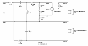
I'm working on a pair of ESS AMT1. One cap is a different value in each pair of speakers. It looks like there are a few versions of this crossover and I'm not sure which caps are original so I'm having trouble figuring out what the values are supposed to be.
Each speaker has two 100uf caps in series. So this position is 50uf.
The other cap is 20uf in one speaker and 16 in the other.
A couple caps are visibly shot so a recap is mandatory.
I'm finding there are many different versions of this crossover. Even a couple different iterations of this layout.
Some have a 20uF cap for the woofer, some have a 55uF cap. With a 20uF cap, the woofer crossover point is 639Hz and the tweeter crossover point is 726Hz.
With a 55uf cap the crossover point is 385Hz. Seems the crossover point the 20uF cap gives makes the most sense?
The value of the inductors are marked slightly differently than on the schematic. One is marked 3.8mH and one 2.3mH. I don't see a marking on the third but it isn't part of the same filter stages the caps are.
Anyone have ideas or additional information? Any other crossover designs for these speakers that might be better?
I'm also interested in hearing about what types of caps people have used and the results from those.
Attachments
Here is a good thread. And a non-associated scheme for an updated xover.
https://www.vinylengine.com/turntable_forum/viewtopic.php?t=100745
https://www.vinylengine.com/turntable_forum/viewtopic.php?t=100745
Attachments
Is this alternate design discussed anywhere?Here is a good thread. And a non-associated scheme for an updated xover.
https://www.vinylengine.com/turntable_forum/viewtopic.php?t=100745
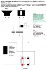
I modelled 3 different designs. Here's another version of the ESS AMT1 crossover. This one looks pretty decent. My instinct is to rip the existing crossover out and build this.
Attachments
Last edited:
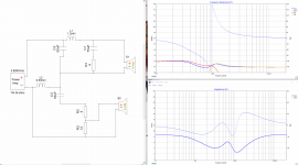
Here's the model of this crossover. Unless I did something wrong, this doesn't look so great.Here is a good thread. And a non-associated scheme for an updated xover.
https://www.vinylengine.com/turntable_forum/viewtopic.php?t=100745
My attempted translation of the German says this crossover was designed with extensive listening tests but not measurement.
Attachments
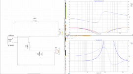
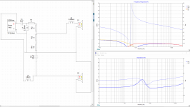
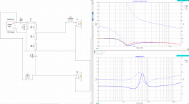
And here's the current crossover. One picture has the 50uf cap for the woofer, and the other has the 20uf cap.
This seems to show a pretty big gap in the response at the crossover point.
I'm not sure why the sys curve looks worse for the 20uf cap even though the curves for the original drivers look better.
This is my first time modelling a speaker crossover like this. Although I studied a lot of filter circuits at university.
These models don't have any info about the properties of the specific drivers in question.
Attachments
Also, the models use 8 ohm drivers and XSim doesn't seem to give me a way to change that to 4 ohm easily. It wants me to find a .zma file instead of just changing a number.
Okay those look a bit better now but #4 still looks best.For your sims in post #5 & 6, invert the tweeter polarity
#5 still looks pretty bad.
Should #4 be inverted as well?
Re:'XSim doesn't seem to give me a way to change that to 4 ohm: - 2 comments
A:from Bill, Xsim designer - "Put your mouse over a component, then right-click your mouse. A menu pops up. Pick the one labeled "tune".
B: You seem to be using nominal impedance rather than actual driver impedance at the xover point in your sims?
A:from Bill, Xsim designer - "Put your mouse over a component, then right-click your mouse. A menu pops up. Pick the one labeled "tune".
B: You seem to be using nominal impedance rather than actual driver impedance at the xover point in your sims?
Is #4 supposed to be a series crossover? If so, I'm not really familiar with series crossovers.
As far as them looking good or bad, you're looking at the transfer functions of the crossover parts. You need to input driver measurements to see how the actual speaker response will look like.
As far as them looking good or bad, you're looking at the transfer functions of the crossover parts. You need to input driver measurements to see how the actual speaker response will look like.
From what I can gather, the schematic in the first post is from the first version of the ESS AMT1. The crossover in post #4 is what they used a bit later, apparently to give better midrange. So it is an ESS design for these drivers. Probably the best bet whether the modelling is exact or not.
Ah, I see now. The crossover in post #4 is not a series crossover. I've never seen anything like it though. It looks like they used one of the inductors as both part of the low pass for the Heil and as part of a notch filter for the woofer
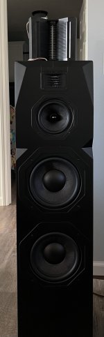
I took a set of emotiva T2 speaks and put the AMTs on top. Bought them used and they had fried tweeters.
There is a 5 1/4 inch midrange driver in those speakers.
Routed the connection from the factory tweeter up through the top and to the HeIl AMT (both are 4 ohm) and did some creative beam tilt to align the mid range and tweeter together. Both moving the Heil backward and lifting the back of the Heil to the height of a pencil lined them nicely.
While I never measured the final response. I can tell you they sound great. A watt is pretty awesome into them!
There is some outside of the box thinking 🤔
Nice! From what I'm reading the Heils are their best in a three way as many don't like their mids.I took a set of emotiva T2 speaks and put the AMTs on top. Bought them used and they had fried tweeters.
There is a 5 1/4 inch midrange driver in those speakers.
Routed the connection from the factory tweeter up through the top and to the HeIl AMT (both are 4 ohm) and did some creative beam tilt to align the mid range and tweeter together. Both moving the Heil backward and lifting the back of the Heil to the height of a pencil lined them nicely.
While I never measured the final response. I can tell you they sound great. A watt is pretty awesome into them!
There is some outside of the box thinking 🤔
Ah, I see now. The crossover in post #4 is not a series crossover. I've never seen anything like it though. It looks like they used one of the inductors as both part of the low pass for the Heil and as part of a notch filter for the woofer
From a few years of trying: I deduced it is the big woofer that gets lost with the mids. I tried active crossovers and separate amps. Moving the crossover points from as low as 700 to as high as 1500. One of those endless quests. It measures ok with sine waves but can’t run fast enough with dynamic material.Nice! From what I'm reading the Heils are their best in a three way as many don't like their mids.
Attachments
looking through notes - look up zobel network. One of those across the woofer helped. Used 4 ohm resistor and 50 uf cap. Filters I wound up with in the pic. The 1 and 10 ohm resistors on the Heil form an L pad. Zobel across the woofer. This one crosses over at 992 cycles. The zobel is a reverse slope for the woofer inductance so it presents a flat load to the crossover.
Just stuff to try. in case your goal is to keep the original configuration and cabinets. That one did a pretty respectable job for us.

Just stuff to try. in case your goal is to keep the original configuration and cabinets. That one did a pretty respectable job for us.
So which caps are worth using? Was thinking of using some higher end caps at for the tweeter, but I'm told both the 50uf and 33uf caps are in the signal path for the tweeter? That would get expensive. Is there any point in using anything other than a solen electrolytic for the woofer shunt?
The client is using a Sansui 2000A receiver for a preamp. I just recapped it for him.
He's got a Kenwood M1 power amp but he is looking at upgrading this.
The client is using a Sansui 2000A receiver for a preamp. I just recapped it for him.
He's got a Kenwood M1 power amp but he is looking at upgrading this.
I’m not sure about the values or location in the network you are talking about. For the one in the drawing in the picture I put up. we used Dayton audio caps and Dayton audio foil inductors. For the Zobel used a mills 4 ohm resistor and again Dayton audio cap. All available at parts express. I’ve never seen electrolytic(s) used in a crossover network. You’d almost have to connect two in series with like polarities together. To make it a non polarized cap.
- Home
- Loudspeakers
- Multi-Way
- ESS AMT1 Crossover. What cap values should I use? So many different versions.