OP, if you are able to measure frequency/phase response, then your design could be done.
only the tweeter elements of the xover will need to be adjusted.
only the tweeter elements of the xover will need to be adjusted.
What are you worried about? Are these so bad that you have to lock your head in one position?
The write up doesn't show that this is the best thing to do, I can't know but trying for the biggest null in reverse may have been simply a guess.you can very clearly see that the phase alignment (with the 14 degree tilt) is in fact excellent.
So, if I make 10° tilt, and if I sit lower, it will be fine?
Vertical dispersion would probably show whats happening with fase, if I am siting lower or higher?
Vertical dispersion would probably show whats happening with fase, if I am siting lower or higher?
Last edited:
Please demonstrate that a deep reverse null at the xo frequency can be achieved without excellent phase alignment of the 2 drivers at or near that xo frequency.no phase data is shown, you cannot make that claim.
a reverse null can be achieved with minimal phase tracking.
That is how i would interpret it....is that 14 degrees may seem like too much but happens to be what is required for these drivers and the xo he has designed for them...
dave
a deep reverse null at the xo frequency can be achieved without excellent phase alignment of the 2 drivers at or near that xo frequency.
when you claim a design has "excellent phase alignment of the 2 drivers", it should not be confined to "at or near that xo frequency".
a design with "excellent phase alignment of the 2 drivers" should have phase alignment well below and well above the xover point.
https://www.diyaudio.com/community/...s-685-loudspeaker-review.302171/#post-7074554
all examples show a reverse null, but with minimal phase tracking
Last edited:
This is getting a little off topic for this thread and a little boring to be honest, but your examples fail to demonstrate your point. In all 3 examples on page 4 from the link to the link you provided (sigh), every single deep reverse null has excellent phase alignment at and close to the xo point.
In simple language, the depth of the reverse null will be determined by the degree of phase alignment at the xo frequency while the width of the null will be determined by the magnitude of the frequency range in which that alignment persists. Also, how wide the null should be is best determined based on the slopes of the drivers' roll-off at the xo, or in other words the degree to which each driver still contributes to the summed response. So a wider null with lower order acoustic roll-off slopes and a narrower null with higher orders.
Back to the speaker in question here, the reverse null between the tweeter and mid is both deep and wide which is an excellent result and can only be achieved with very good phase alignment at the xo point and within the full frequency range of the summed contribution from each driver. Here's the graph:

Although the phase info has not been included, this clearly shows excellent phase alignment while the SPL of each driver's roll-off is still less than about 15dB down from the summed response, or from about 800Hz to 7kHz. In my experience, that's actually quite an outstanding result.
For the OP, I haven't actually drawn out the geometry, but if the baffle tilt is 14 degrees when you are level with the center of the tweeter, then if you only slope it 10 degrees, intuitively it would seem you'll maintain the same conditions between the tweeter and mid if you listen 4 degrees below the tweeter level whether you lower your chair or raise the speaker.
In simple language, the depth of the reverse null will be determined by the degree of phase alignment at the xo frequency while the width of the null will be determined by the magnitude of the frequency range in which that alignment persists. Also, how wide the null should be is best determined based on the slopes of the drivers' roll-off at the xo, or in other words the degree to which each driver still contributes to the summed response. So a wider null with lower order acoustic roll-off slopes and a narrower null with higher orders.
Back to the speaker in question here, the reverse null between the tweeter and mid is both deep and wide which is an excellent result and can only be achieved with very good phase alignment at the xo point and within the full frequency range of the summed contribution from each driver. Here's the graph:
Although the phase info has not been included, this clearly shows excellent phase alignment while the SPL of each driver's roll-off is still less than about 15dB down from the summed response, or from about 800Hz to 7kHz. In my experience, that's actually quite an outstanding result.
For the OP, I haven't actually drawn out the geometry, but if the baffle tilt is 14 degrees when you are level with the center of the tweeter, then if you only slope it 10 degrees, intuitively it would seem you'll maintain the same conditions between the tweeter and mid if you listen 4 degrees below the tweeter level whether you lower your chair or raise the speaker.
below i have attached a graph from the above link you have read.

although you seem to percieve it as "excellent phase alignment", it is not, the phase tracks merely from 1.5K to 3K
the thread below shows examples of far better phase alignment
The importance of phase tracking
in the above thread, post 9 with the graph labeled "A_phase_2nd" shows tracking from 400Hz to 5K
in the above thread, post 19 the graph shows tracking from 700Hz to 8K
My "excellent phase alignment" quote was about Troels' speaker not the one you linked to. (sigh again)
What I said about the graphs you linked to was that "every single deep reverse null has excellent phase alignment at and close to the xo point". Here are the FR and phase graphs together this time for one of the examples you linked to:

The xo is at ~2500Hz and the phase matches perfectly at that frequency and within the frequency range I have highlighted. In this example the width of the reverse null is not as wide as with Troels' design though, but it's still much better than no alignment in the xo region at all.
I am still open to being shown that a deep reverse null can be achieved without good phase alignment in that xo region. Always interested in learning something new.
What I said about the graphs you linked to was that "every single deep reverse null has excellent phase alignment at and close to the xo point". Here are the FR and phase graphs together this time for one of the examples you linked to:
The xo is at ~2500Hz and the phase matches perfectly at that frequency and within the frequency range I have highlighted. In this example the width of the reverse null is not as wide as with Troels' design though, but it's still much better than no alignment in the xo region at all.
I am still open to being shown that a deep reverse null can be achieved without good phase alignment in that xo region. Always interested in learning something new.
What say about the third order Butterworth?
Phase tracks perfectly with a 90 degree phase shift. There is no null for either standard or reverse polarity.

Phase tracks perfectly with a 90 degree phase shift. There is no null for either standard or reverse polarity.
They track well but they are not what one would call aligned; they do not share the same phase angles at the same frequencies in the xo region. Therefore, no reverse null to speak off. Note I'm not commenting on the validity of the xo, only on the nature of the reverse null.
That is the reason that this kind of alignment offers flat response and flat power (on and off axis) at the same time.
First of all, thank you guys for patricipation in this discusion, but I am starting to feel like a ''golden retriver'' (means I am tech. not on this level of discusion 😀 )For the OP, I haven't actually drawn out the geometry, but if the baffle tilt is 14 degrees when you are level with the center of the tweeter, then if you only slope it 10 degrees, intuitively it would seem you'll maintain the same conditions between the tweeter and mid if you listen 4 degrees below the tweeter level whether you lower your chair or raise the speaker.
this quote from jReave is what I thought in the begining. How often I am going to be in perfekt liesening position? +/- 3° (left, right, up, down). Speaker schould perform in this range least 95% performanse?
Anyway, I did some new 3D box designs, and original 14° tilt for whole enclosure will be ok (from aesthetic stand point) so only change will be woofer mowing forward approx 10cm and under 14° angle:
Can you guys give me you final thoghts on this, so i can start with project, without changing XO.
Last edited by a moderator:

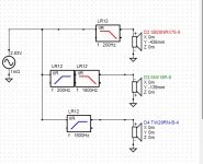
For what it’s worth: Here's a first cut simulation showing what might happen when the woofer is moved ahead toward the listener by 10 cm.
1. The simulation uses perfectly flat driver responses and text book filters that match Troel's 200/1600 Hz crossover points and LR12 slopes. No baffle step effects were included. This shouldn't be an issue since we're just interested in the change in response when the woofer is moved.
2. I used the tweeter as the design axis so its position is 0, 0, 0. I calculated the Y values for the mid and woofer. I did it on a plane so you may want to verify.
3. I assumed the cabinet slope puts the mid and tweeter on the same acoustic plane so the mid's delta Z = 0.
4. The woofer's acoustical offset is unknown in the original position so I used a value of zero.
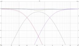
I attached the crossover diagram and a response diagram. The response diagram shows the original responses (woofer Z offset = 0) with dashed lines and the modified responses (woofer Z offset = -10 cm) with solid lines. I was somewhat surprised where the biggest change (~ 1 dB @ 600 Hz) occurred.
For a 2nd cut simulation I’d start with manufacturer’s IB plots, add the simulated baffle step responses and use minimum phase versions. You could even add in the driver’s simulated low end responses if desired. The still unknown variable would be the woofer’s acoustic offset.
1. The simulation uses perfectly flat driver responses and text book filters that match Troel's 200/1600 Hz crossover points and LR12 slopes. No baffle step effects were included. This shouldn't be an issue since we're just interested in the change in response when the woofer is moved.
2. I used the tweeter as the design axis so its position is 0, 0, 0. I calculated the Y values for the mid and woofer. I did it on a plane so you may want to verify.
3. I assumed the cabinet slope puts the mid and tweeter on the same acoustic plane so the mid's delta Z = 0.
4. The woofer's acoustical offset is unknown in the original position so I used a value of zero.
I attached the crossover diagram and a response diagram. The response diagram shows the original responses (woofer Z offset = 0) with dashed lines and the modified responses (woofer Z offset = -10 cm) with solid lines. I was somewhat surprised where the biggest change (~ 1 dB @ 600 Hz) occurred.
For a 2nd cut simulation I’d start with manufacturer’s IB plots, add the simulated baffle step responses and use minimum phase versions. You could even add in the driver’s simulated low end responses if desired. The still unknown variable would be the woofer’s acoustic offset.
Attachments
- Home
- Loudspeakers
- Multi-Way
- Speaker KIT changes (your analysis)