For an oxide coated signal valve: If you can regulate to 1%, then setting the nominal output to ca. -2% will give very near to the maximum lifetime, and the least deviation from operating performance. A nominal voltage anywhere from -2% to -4% will likely make little difference to that for most cases.
6.3VI didnt see it yet; Is there a consensus on the 'best' operating voltage for 6.3V types?.
(assume DC and that we can regulate to better than 1%).

If "best" includes ease of implementation, then 6V.
All of my builds use 12V and series pairs for ease of implentation except for my Little Miracle which uses a 7806 for each 6F12P heater.
There are also a pair of monoblocs I built years ago that run the heaters at 11.4V which have worked fine the entire time.
There was a BBC article (or Bell, I can't remember) where they settled in -10% heater voltage for maximum lifetime. Some of the tubes tested as new 80 years later when they decomissioned it which makes me think it is BBC.
Klausmobile has a bunch of curves comparing 6.3V with 5V - slightly lower emission as expected but in some cases added to linearity.
Here are their tests of the 6N8S: http://klausmobile.narod.ru/testerfiles/6n8s.htm
I'd read something similar to this years ago, similarly with kodabmx's post above.. it always stuck in my mind and I shoot for 6V.For an oxide coated signal valve: If you can regulate to 1%, then setting the nominal output to ca. -2% will give very near to the maximum lifetime, and the least deviation from operating performance. A nominal voltage anywhere from -2% to -4% will likely make little difference to that for most cases.
Cheers.
I thought heater voltage does not affect lifetime of an indirectly heated tube because the tube lifetime is limited by the emission of the cathode, excessive grid leakage, or loss of vacuum, not the heater burning out prematurely.
As long as you adjust the bias of the tube correctly, it doesn't really matter. Emission of the cathode only increases if you allow it to by not adjusting the biasing appropriately. If you run the heater hotter, then the cathode will more readily emit electrons so you'll need a more negative bias voltage on the grid to keep the cathode emission in check. Fixed bias might be more susceptible to becoming over-biased (or under-biased) with variations in filament voltage due to line voltage increasing.
Otherwise, having a high heater voltage just wastes power and causes the tube to run slightly hotter which would degrade the peak inverse anode voltage and maximum power handling - obviously not below the specs if the heater voltage and everything else remains within limits.
Last edited:
One issue is that higher heater temp means higher cathode temp means quicker exhaustion of the emissive oxides on the cathode.
In this way higher heater decreases tube life even if heater doesn't burn out.
Jan
In this way higher heater decreases tube life even if heater doesn't burn out.
Jan
This is certainly the main reason for keeping the heater voltage at or slightly below nominal value.heater temp means higher cathode temp means quicker exhaustion of the emissive oxides on the cathode.
The same process affects the low-end voltage limit. In this case, the subsurface barium does not reach the surface in sufficient amounts to sustain emission over very long operating periods. You might not notice any problems in the short term, but since we have been talking about the ideal operating voltage, -5% should be considered best practice for the low-end limit (though -10% may also be OK in other cases).
This is expressed directly in the data sheet of the E180F - a «special quality» pentode, with a 10000 hour lifetime rating:
.
So the data sheet from the people who make the tube state "Variation in heater voltage exceeding the range of 6.0V to 6.6V will shorten the life of the tube" but then here some people are claiming the tube life will be "Drastically shorter" at even 6.45V.
I just don't buy that tube heaters need electronic voltage regulation to exactly 6.3V or they will quickly burn down. The tubes themselves aren't made this precise.
I just don't buy that tube heaters need electronic voltage regulation to exactly 6.3V or they will quickly burn down. The tubes themselves aren't made this precise.
6.45V is OK for the E180F as part of the mains Line voltage tolerance. But to get the 10000 hour lifetime, the [10000-hour] Time-averaged voltage must still be 6.3V - and this will usually mean setting it to 6.3V (at nominal line voltage) by design.but then here some people are claiming the tube life will be "Drastically shorter" at even 6.45V.
This is simply a valve design that works to the power supply tolerance in its target market: in the 1950s-1970s, western world's line voltages were mostly ±5%.
A time-averaged voltage works because the barium transpiration from the subsurface slows down at low voltage, and speeds up at high voltage. To an extent, they highs and lows must cancel out.
The degradation of line voltage tolerances to ±10%, in Europe, will undermine this, depending on how bad it is in practice, for your location.
No doubt some DIYers think this is too much fuss - and that's fine, just build. This is DIY.
But at least one person wanted to know what the optimum voltage was, so no apologies are due for stating it.
Practically speaking,
If I am making a guitar amp for someone to have fun with, or an amp build with the cheapest ebay valves, I'll just run them AC as near to 6.3V as it falls, and let the mains fluctuations fall where they may.
But if I build a high quality RIAA preamp with pristine Marconi-Osram Z729s, I will certainly want to get the absolute best lifetime from them. And that means DC and regulation (or stabilization) at 6.3V or a little below.
So we debate for pages and question the manufacturers advice/data sheets that 6.3V is the nominal voltage for longest tube life? And we apparently try to hide our own sloppiness/lazyness/inability to do things precise by saying that higher or lower voltages do not matter? This while it is only about the heaters, what to expect when it is about the circuit itself? 🙂 It does not come as a surprise that many design by just soldering random value parts together.
This while making a stable regulated nominal 6.3V costs less time than reading this thread.
This while making a stable regulated nominal 6.3V costs less time than reading this thread.
Last edited:
You can take this as far as you fancy. There are those that feel that DC has a downside in that it always 'scrapes' the heater inside the cathode tube to the same side at switch-on causing mechanical fatique over time.
You can find circuits people use with DC heaters that reverse the polarity at each switch-on.
Jan
You can find circuits people use with DC heaters that reverse the polarity at each switch-on.
Jan
Yes some fancy to look at minuscule details while overseeing basic stuff. Didn't mention AC or DC but I guess the DC versus AC debate will never stop. AC has the "problem" that it goes up and down with mains voltage. When going for DC it costs no sweat to make it 6.300V if one wishes as it is a maximum of 2 resistors with 1% tolerance that determine that. Your TPS5402 and TPS54331 circuits probably have exact DC 6.3V output voltage with slow start?
I see a Didden 6.3V regulated AC filament PSU in my crystal ball 🙂
I see a Didden 6.3V regulated AC filament PSU in my crystal ball 🙂
Last edited:
Where does any data sheet say this? And from my measurements of various tube filaments, the construction varies more than some people seem to believe the voltage specs need to be held at.6.45V is OK for the E180F as part of the mains Line voltage tolerance. But to get the 10000 hour lifetime, the [10000-hour] Time-averaged voltage must still be 6.3V - and this will usually mean setting it to 6.3V (at nominal line voltage) by design.
Can you please refrain from PERSONALLY insulting people here?So we debate for pages and question the manufacturers advice/data sheets that 6.3V is the nominal voltage for longest tube life? And we apparently try to hide our own sloppiness/lazyness/inability to do things precise by saying that higher or lower voltages do not matter? This while it is only about the heaters, what to expect when it is about the circuit itself? 🙂 It does not come as a surprise that many design by just soldering random value parts together.
This while making a stable regulated nominal 6.3V costs less time than reading this thread.
It's not "sloppiness/lazyness/inability to do things" nor do we "solder random value parts together" in the rest of the circuit. It's that we realize a couple of % points on either side of optimal on the heater voltage has no real impact on the system, it's a waste of time and money building complex regulated heater supply circuits and instead focus attention of the parts of the circuit that actually do matter.
Many things in electronics or in general don't have "real impact " but we do them anyway . More heat = shorter life , this is obvious , by how much it is hard to say , nobody cares about a light bulb being overheated because of high mains , but tubes are more than that for some people .
Last edited:
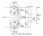
.. and to a similar end, using independently heated tubes and +/- 6V supplies for increased common mode rejection, and swapping tubes between channels every now and then.You can find circuits people use with DC heaters that reverse the polarity at each switch-on.
I don't underestand this. What does it mean?[]using independently heated tubes and +/- 6V supplies for increased common mode rejection, []
Jan
I don't underestand this. What does it mean?
Jan
https://www.diyaudio.com/community/...a-thoroughly-modern-tube-phono-preamp.163570/
See Fig 7, and related paragraph above.
Cheers
Attachments
Jan, irrespective of real or imagined, is this scenario something a slow start circuit would mitigate?You can take this as far as you fancy. There are those that feel that DC has a downside in that it always 'scrapes' the heater inside the cathode tube to the same side at switch-on causing mechanical fatique over time.
Thanks.
- Home
- Amplifiers
- Tubes / Valves
- Heater Voltage too much?