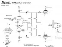
Hi to all tube experts out there. Im building triode dick design pushpull 807 amp exactly on dicks plan but I run in some problem. On the driver stage that Im using 12sl7 tube the top triode section(one half of 12sl7) is working without problem, the bottom half(triode) make me problem becouse I mesure on the cathode 0 volts. So the top triode I have on anode 365volts before 180kohm resistor and 210 volts after 180kohm resistor so direct on anode, on cathode I have 2,4 volts and its all OK. On the bottom triode I have 365 volts before 180kohm resistor and 360 volts after direct on the anode and on cathode I have 0 volts. I checked 5 times all wiring, I put two pairs of another 12sl7 tubes in there and the problem is the same on both channels. So plese look on the schematic. Is there some error in the schematic or I made some mistake?
Attachments
Last edited:
The bottom 6sl7 is not pulling any current. Schematic looks ok... What voltage do you have on the grid of the lower valve. Can you post a picture of the socket wiring?
With the power off, is there about 270k ohms resistance from the lower 12SL7 grid to ground?
The grid may not have a DC path to ground.
The grid may not have a DC path to ground.
I mesured the resistance also from bottom grid to ground but it jumping from 6 to 7 mohms, and its not stable.
As you can see, there are resistors connected to that grid that eventually go to ground.
Connect the (-) meter lead to ground. Start at the grid with the (+) lead and check at all
of the nodes where the resistors connect. The readings should be a few hundred k ohms.
There may be a bad connection, especially around the 1k resistor.
Or, you may have a leaky coupling capacitor. Lift one lead of both coupling capacitors,
and recheck the resistances.
Hi, yes the resistors are there 220 kohm 2x and 22 kohm 1x but in the schematic this are not conected to ground, or I just dont see this?
Look at the junction of the 330k resistors. That point is grounded.Hi, yes the resistors are there 220 kohm 2x and 22 kohm 1x but in the schematic this are not conected to ground, or I just dont see this?
When measuring from either end of the 1k to ground, the reading should be around 275k.
But let the power supply decay for a few minutes before measuring the resistance.
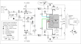
Ups guys, I forgot to say that Im using from tentlabs fix bias module. So I dont use the 330ohm cathode resistors and baypass caps. Yes I see I made a mistake.
Yes, they should all behave the same since the problem is not in the tube.And the problem is on both channels with all 12sl7 tubes that I have at home.
Can't say until you post the entire correct circuit here.I think I must ground the 220 kohm resistor, or??
But don't operate the amp any more until this is fixed, as it could damage the tubes.
The schematic is to 90 % the same with all parts like in schematic, the diference is that Im not using cathode resistors and bypass caps on the 807 cathode, but the cathode is conected to tentlabs negative bias supplay and the negative bias supply is then for each tube conected thru 330 kohm resistor to screen with 1 kohm screen resistor. So in this way I can adjust the negative bias supplay to each tube. This is the only diference that I made, becouse I have this tentlabs bias supply at home.
I do not know how that -22V appeared at the grid, but it explains the tube not conducting. I ask for a picture🙂
On the scematic the bottoms of the 330kohm resistor are conected to tentlabs negative bias module and the cathodes also.
- Home
- Amplifiers
- Tubes / Valves
- 807 tube PP Triode Dick amp need help