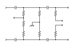
The amplifier's topology requires that the 330k resistors go to 0VDC, and to use self bias for the output tubes.
That 0VDC is needed for the lower tube's grid, for proper DC bias.
This type of phase inverter may be incompatible with the bias module.
About the only way to make this particular circuit work with the bias module
is to use two series coupling capacitors in each phase, with the resistors connected
to the junction of the capacitors. Another pair of resistors would be needed
after the second capacitor from the output tube grids to the bias module.
Attachments
Last edited:
Aham! The 330k should return to gnd, so that the grid of the lower valve is also at gnd. Now the 330ks return to the negative bias voltage, explains why the value at the grid is -22V
Sorry erik its verry dificult to see from the picture if I post but I checked truly all wirings but this is the first time I build some PP amp, I made several SE with 300b,45 triode and 2a3,so this is first build with 807 tetrode becose I just become this for free from my good buddy and Im building now this amp for him.
Yap, so my stupid mistake, no problem, i take out the tentlabs bias module and put in the resistors and bypass caps. Yap thats the way to go.
See post #21.Yap, so my stupid mistake, no problem, i take out the tentlabs bias module and put in the resistors and bypass caps. Yap thats the way to go.
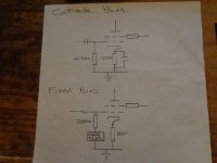
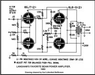
I thought you had an issue with the 6SL7? Anyroad, cathode bias - grid leak & cathode resistor go to ground. Fixed bias - grid leak resistor goes to negative voltage source (-25v to -40v ish) cathode direct to ground, see pic (grid stopper not shown for clarity. Grid leak resistor can be bigger for cathode bias, needs to be smaller for fixed, see STC 807 application report.
You can use a combination of fixed and cathode bias, I did this on my last 807 amp, it works well.
Hope that helps Andy.
You can use a combination of fixed and cathode bias, I did this on my last 807 amp, it works well.
Hope that helps Andy.
Attachments
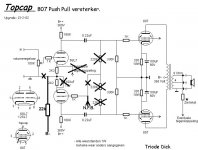
Hi Andy, thanks for help, I have problem yes with 12sl7 becose if you look on schematic from triode dick I have used negative bias supply insteed of resistor/capacitor on 807 cathode and this way the 12sl7 bottom triode is not working properly.
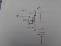
Right, got you, the 6SL7's get their control grid ground references via the two 330k OP valves grid leaks. However if you route your negative bias supply through a pot so to vary bias that should work, see pic. You may have to swop the 330k's for 220k's.
Andy.
Andy.
Attachments
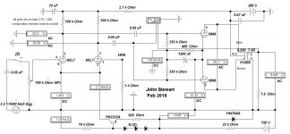
Hi Andy, plese look at tentlabs schematic how to use negative bias supply. Its also PP amp but with el34 and 6n1p for driver. My question. Can I use something like that in my design with this bias supply??
You can convert the driver tubes to LTP phase inverter, by using the Tent Labs negative supply. The 1k grid resistor of the lower tube goes to GND, the 2.2 resistors go to another resistor R (instead of GND) that goes to the negative supply. The 220k resistors and the 22k is not needed. Calculate R so that the idle current of the phase inverter is the same as in the original circuit.
The grid voltage in this application with fixed bias is about -35V, so I suppose the negative supply voltage is about -50V. I would start with R = 22k, change as needed.
The 100uF capacitor is not needed either.
The grid voltage in this application with fixed bias is about -35V, so I suppose the negative supply voltage is about -50V. I would start with R = 22k, change as needed.
The 100uF capacitor is not needed either.
Last edited:
I just proposed a better alternative to the current phase inverter, that has issues when you bias the output tubes' grid negative. Something like this:Hi, Im using the tentlabs negative supply for bias the 807 output tube, no 12sl7 driver tube.
Attachments
Last edited:
Aaaah, OK. Yes this is another option also. I will first put in the cathode resistor/baypass cap on 807 cathode and conect everything like in original schematic from triode dick and mesured al the voltages and than to look how it will sounds.
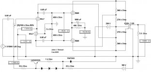
Like those posted in a thread from 2019? During late winter & spring of 2019 I tried several experimental versions of amps essentially like this one.I just proposed a better alternative to the current phase inverter, that has issues when you bias the output tubes' grid negative. Something like this:
Some of the drivers were differential, some with tails to -150V, others had an NPN tail. Still others with the split load inverter.
All built on an inverted cake tin, so named the Betty Crocker special. I wouldn't do a cake tin again, very inconvenient.
The pin outs of 6SN7, 6BX7, 6BL7 & 5998 are the same so it was possible with minimal change to check the performance of all.
All the test results are here on DIY. More recently the Betty Crocker has been rewired for a pair of 6EA7/6EM7s.
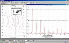
All of the tests are in Class A while the Pd is not exceeded. With these conditions the 6SN7 was good for about One Watt.
The 6BX7 & 6BL7 managed 3W. The 5998 did >10W at clipping. I used a lab supply for power.
And for those who value measurement results, some for IMD & THD. 😉👍
Attachments
-
 Boot Strapped 5998 6SL7 Amplifier at 4.8 Watts.JPG72.5 KB · Views: 117
 -
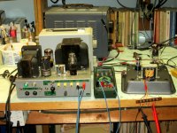 IMG_3997 Betty Crocker 5998 Amp on the Bench.jpg382.2 KB · Views: 98
 -
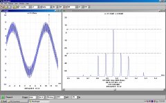 PP 5998 Amp 3 Watt IMD 80 Hz & 5 KHz.JPG112.2 KB · Views: 81
 -
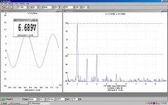 PP 5998 Amp 6W 1.46% 3H.JPG104.5 KB · Views: 82
 -
 PP 5998 Amp w 15V Neg Drain.JPG71.4 KB · Views: 89
 -
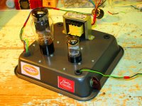 IMG_3996 Betty Crocker 5998 Version.jpg313.4 KB · Views: 99
 -
 PP 5998 Amp 10 Watts OPT Taps 1-5.JPG113.3 KB · Views: 102
- Home
- Amplifiers
- Tubes / Valves
- 807 tube PP Triode Dick amp need help