Hi there
can you model ‘ports’ (that is to say channels from the chamber of a synergy horn, which radiate into a point offset further along the horn’s length) in Hornresp?
thanks
can you model ‘ports’ (that is to say channels from the chamber of a synergy horn, which radiate into a point offset further along the horn’s length) in Hornresp?
thanks
A good question. I think I can set a ported rear chamber in hornresp, but I'm not sure if hornresp assumes the port is external to the horn and just adds it to the horns output.
Hopefully somebody who knows hornresp better than me will chime in.
(I'm off to double check the help file)
Just checked and I modelled as an offset driver horn with ported rear chamber in my model..
Rob.
Hopefully somebody who knows hornresp better than me will chime in.
(I'm off to double check the help file)
Just checked and I modelled as an offset driver horn with ported rear chamber in my model..
Rob.
Last edited:
No.can you model ‘ports’ (that is to say channels from the chamber of a synergy horn, which radiate into a point offset further along the horn’s length) in Hornresp?
As Rob has indicated, and as shown in the attachment below, Hornresp simply combines the output from the rear chamber port with the output from the horn.
Attachments
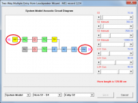
Just to clarify - I have assumed that you are referring to a port in the rear chamber behind the ME1 offset driver, and not to a port in the throat chamber (which of course does feed into the horn at the designated offset point).can you model ‘ports’ (that is to say channels from the chamber of a synergy horn, which radiate into a point offset further along the horn’s length) in Hornresp?
Attachments

While I have your attention David 😀...
Is there a reason why particle velocity is greyed out when I have the rear chamber ported ?
Thanks,
Rob.

Is there a reason why particle velocity is greyed out when I have the rear chamber ported ?
Thanks,
Rob.
Is there a reason why particle velocity is greyed out when I have the rear chamber ported ?
Hi Rob,
Sorry for the delay in replying, I missed seeing your post until now 🙂.
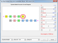
The Particle Velocity menu command is greyed out because the combined response is being displayed. Use Tools > Output to select the desired output and the Sound Pressure and Particle Velocity menu commands will then be enabled for that output.
Kind regards,
David
How does one calculate the size of the ports in the throat chamber? Is it relative to 1/4 the size of the lowest wavelength you want to exit into the horn? Is there a reason many are rounded rectangles instead of circles? Should they be from the edge of the cone?Just to clarify - I have assumed that you are referring to a port in the rear chamber behind the ME1 offset driver, and not to a port in the throat chamber (which of course does feed into the horn at the designated offset point).
I haven't been able to find a good resource and plan on experimenting on a synergy design with spare drivers.
Don't ask me, I have no idea 🙂.How does one calculate the size of the ports in the throat chamber?
Hopefully someone with practical experience building a MEH system may be able to help out.
How does one calculate the size of the ports in the throat chamber? Is it relative to 1/4 the size of the lowest wavelength you want to exit into the horn? Is there a reason many are rounded rectangles instead of circles? Should they be from the edge of the cone?...
I think that the answer to your question actually involves an engineering trade of the same class of Hofman's Iron Law . I find that most people come down on these trades as if the subject is almost religious (i.e., no longer based on rational decision criteria). Good engineering tradeoff considering all tradeoff factors has been the gateway to higher sound quality success, in my experience....Hopefully someone with practical experience building a MEH system may be able to help out.
The MEH port size tradeoff involves setting design parameters directly affecting at least two MEH performance capabilities, i.e.:
1) overall driver/horn efficiency, and
2) polar coverage at the frequency band around the 1/4 wavelength axial distance to the horn throat from the off-axis ports (the lower frequency drivers in an MEH having ports not coincident with the horn throat).
If one believes that polar coverage consistency is paramount and horn/driver efficiency is not, then what you see as a result are little slits and port plugs with multiple holes for the off-axis ports, thus compromising effective port area to the detriment of horn/driver efficiency.
If on the other hand, one considers the overall effects of off-axis driver efficiency to be paramount (see Olson's figure 7.2 in his Acoustical Engineering text for reference), and understands most of the issues with accepting a much lower efficiency from the lower frequency drivers (...it seems to be fashionable nowadays to downplay the loss of overall efficiency), then what we see is large off-axis ports with the realization that some loss of off-axis polar coverage at the acoustic crossover/low pass frequency band will be inevitable, and that this local loss is acceptable/inaudible.
In a nutshell, that is the tradeoff, but most here seem to want to oversimplify this tradeoff. My experience has been that a rational tradeoff between these two performance parameters is the most successful. There is a rule of thumb that says that the ratio of the driver diaphragm area to its corresponding off-axis port throat area on the MEH should be no larger than 10. If you look at Olson, you can see why--the falloff in efficiency with Ad^2/At is rapid and significant as a function of driver voice coil mass.
As far as shape of the ports are concerned--as long as the ports themselves do not create port chuffing or significant parasitic losses due to drag, etc., this aspect of port design is much less important to the overall sound quality of the MEH loudspeaker.
Chris
Last edited:
By the way, elongating the off-axis (usually woofer) ports along the corners of the horn is actually a trade in itself: trading the polar coverage loss at the 1/4 wavelength low pass (throat bounce) band with lower frequency loss of polar coverage. This is usually a good trade since the relative area of the elongated woofer ports to the horn cross-sectional area continues to decrease along the horn path expansion (assuming the port width slots do not expand with the horn expansion, but are rather a fixed dimension). So the effects of the off-axis port reflectivity loss can be spread out. Another issue is whether or not the effects of the long and thin off-axis ports begin to affect the time alignment of the woofer ports, with the portions of the ports closest to the listener arriving before the portion of the ports closest to the horn throat.
Another trade is to place the off-axis posts on the upper and lower sides of the pyramidal horn (as opposed to the sidewalls), which puts more directivity loss into the vertical axis, where the variation in listener possible positions is usually less than in the horizontal axis. There are some psychoacoustic studies that suggest that horizontal directivity control/consistency is perceived more acutely by the human hearing system than in the vertical direction. Additionally, in most listening rooms, the minimum dimension of listening rooms is usually in the vertical axis (i.e., ceiling bounce), so the local decrease in polar coverage at the crossover frequency band is likely perceived as less detrimental than in the horizontal direction.
The balancing trade of course is whether or not the woofers can be mounted to the horn and fully inside its back box when placed in the vertical axis if the horn is not square but rather elongated in the horizontal direction, i.e., a 90 x 60 degree coverage horn would be oriented with the long axis horizontally in-room to get 90 degrees coverage horizontally and 60 degrees vertically to match the psychoacoustics needs and minimum coverage requirement orientation to the room's minimum dimension (usually vertically).
Do note however that the loss of polar coverage in the crossover region due to the area of the off-axis ports does affect both acoustic output axes of the horn, not just the axis in which the woofers are oriented. But the effect is more pronounced in the direction of the mounted driver axis.
Chris
Last edited:
I've had good luck with ports that are 1/8th of driver Sd.How does one calculate the size of the ports in the throat chamber?
This has worked well for 4" mids, as well as cones from 8" to 12"
Rounded rectangles are used to get the ports close into the horn corners, where the ports presumably have less of a disruptive effect on the frequencies originating deeper in the throat.Is there a reason many are rounded rectangles instead of circles? Should they be from the edge of the cone?
When the ports are put in the corners like that, it gets difficult to mount drivers where the ports don't fall under the edge of the cone or surround.
fwiw, I've tried a number of port placements, shapes, and sizes .....in the horn corners, out in the middle of the horn walls...etc....
Corners may be optimal for smoothest polars....but even that i still dunno...
I do know synergies are a heck of a lot easier to build and keep weight down, when larger cones (8-12") ports are out in the middle...so that's what i've been doing..
Hi All
I am actually considering to place four 16 ohm bass-drivers in the "upper and lower sides of the pyramidal horn (as opposed to the sidewalls)". One for each corner.
That makes for freedom of placement. I am not particularly fond of placing the ports under the surround. With one woofer for each corner, I can place the port more in the center of the woofer. Or put the other way around, place the port optimally in the horn, and place the woofer optimally on top of the port!
This project for me is not a budget project anyway, so whether I buy four 8 ohm drivers or eight 16 ohm drivers is not paramount.
Unfortunately progress is slow in my end, but the hope is still alive😉. I am working on making a workshop to build the horns, as I need more space.
This summer I visited a danish member, schlager, who has build some really big synergies with a lot of bass-capability in the form of multiple bass-horns. That was so much fun. I could turn up the volume, and the sound stayed the same, no compression and no sign of strain. Effortlessness😀.
Steffen
- Home
- Loudspeakers
- Multi-Way
- Multiple entry/synergy horn with ‘ports’ - Hornresp?