Hi Nounouchet
The manual recommends >= 1A even though it could be less. I would use 30VA as a minimum since price difference at that power is not very significant and lower Power transformers have a worst load regulation.
Keep us posted on your build.
Fab
The manual recommends >= 1A even though it could be less. I would use 30VA as a minimum since price difference at that power is not very significant and lower Power transformers have a worst load regulation.
Keep us posted on your build.
Fab
For dad Fab.... a new USSPA
Hello everyone, a few days ago I received the PCBs thanks to the courtesy of Fab who already has a new child since last Sunday even if he does not know it
: D
The preamplifier (USSPA 1) is very promising, after a proper break-in I will report my listening impressions ... Thanks again Fab.
Hello everyone, a few days ago I received the PCBs thanks to the courtesy of Fab who already has a new child since last Sunday even if he does not know it
: D
The preamplifier (USSPA 1) is very promising, after a proper break-in I will report my listening impressions ... Thanks again Fab.
Attachments

Well done, Fabio!
Let us know how it sounds, this is supposed to be a very good preamp...
Claude
Let us know how it sounds, this is supposed to be a very good preamp...
Claude
Nicely done Fabio! I also enjoy the "2"version 😉
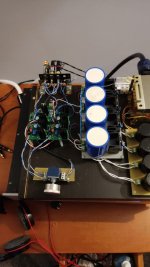
What brand are the psu capacitors, they are Fatties!!
What brand are the psu capacitors, they are Fatties!!
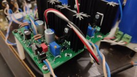
Hi, it is sounding ... for now I can only say that it sound good, the soundstage is good in three dimensions, the tonal balance is correct, the dynamics are decent, but overall the sound appears a bit tied. It's changing for the better minute by minute. Too early to judge. The power supply uses silicon carbide diodes, 4-pole Mundorf AG + 6800uf and 4-pole claritycap TC4 100Uf, the regulators are belleson. It is one of my strengths.
Attachments
Hi Pinocchio, you see well, these 4-pole capacitors, they are really special and I think this preamp is special and that will be followed by the version with the Sanken, first I need to recover some 2sk170 and 2sj74 then surely I will make it ... maybe together to a USSA.
A small update just to say that I couldn't understand why after the burn in the preamp was still sounding muffled, not rich and natural enough compared to expectations. Thanks to Fab's help, I first reduced the value of the input cap to 47pf and then I checked the jfet that I had bought from Lubicalvin some time ago and here the surprise ... they were the culprits, they weren't well matched. Now the USSPA sounds very good, rich, transparent detailed. The micro-contrast is of an excellent level. Right now, I'm powering it at 12v because I have been comparing it with a preamp of juma, user of diyaudio, using the same power supply, later on, I'll let you know how it goes by getting the power to 15v and I will give you a detailed build report. Fab, you are a magician! Thanks, Fabio.
Hi Fabio
I am glad I could help identify the main issue. I even think that the previous jfet you had installed do not really have the j74 typical transconductance curve….I had the same issue with the same specific source where the jfet were extracted from another dual package….
I do not believe in magic but I accept the compliment!
Now you can enjoy the music.
Fab
Today, I build the USSPA1 board. Can someone advise how toadjust the BIAS, do i need to keep the positive and negative probe of the multimeter across R13 or R14 and adjust the P1 or P2 respectively.
Hi
see attached extract of the USSPA manual Test section:
”
11 TEST
Output bias and dc offset are adjusted simultaneously using P1 and P2.
Install one meter probe lead on either R13 (close to Ouput transistors) or R14 (close to output transistor). Install the other meter probe lead on V+ (if R13) or V- (if R14). Install another meter probes set between Output and Ground.
Turn P1 or P2 to center DC offset to < 5mv.
Turn P1 in one direction and then P2 about the same amount in same direction to increase (or decrease bias).
Turn P1 or P2 just a bit ( to prevent changing too much the bias) to re-center DC offset. Wait until bias (temperature) stabilization (about 30 minutes) and readjust bias/DC offset if necessary.
Optimal bias is 50ma and more (refer to schematics of USSPA1 and USSPA2).”
Good luck
Fab
hi fab
My friend Fabio (fabiodipietro27 member) made me discover your USSPA project. The reason that affected me to this pre-line was my need to use it as part of the analog section of my DAC with a sufficient gain after the execution of the I/V conversion (the DAC adopts the PCM1704 and the conversion takes place using the 'Opa861). The task had been assigned to some candidates all put on par to compete for the primacy. My main goal was to have the best and at the end of long tests the best was the USSPA-1 equipped with the Mosfet Toshiba J313/K2013. The most interesting thing for me was that I wanted a pre -line without coupling condensators on the signal. Not only was this goal centered, but the reinforcement quality of the USSPA is absolutely extraordinary. All aspects of reproduction are brought and valued at the highest level. My DAC uses PCBs entirely designed by me and initially I built the USSPA using the PCBs made available by Fab. However, as I wanted to make small changes and above all having a sufficient number of PCBs to compare by adopting other active components I thought of drawing them on their own. So I got the freedom to have my PCBs. I do not intend to compete with the author in the least. They are mine, for exclusive personal use. I still haven't understood well if the usspa-2 with the Sanken I like it more, I need other tests. What I have left to ask Fab, while I congratulate him for the exceptional performance of the USSPA which will be a reference for me, is this:
I wanted to try the FQP3N20/FQP3P20 mosfet. What values should I use resistance on the circuit to be able to use them? For now I have tried to put a 22 -ohm R on the source but I can't perform the size of the bias.To tester marks zero mV

This is original PCB

My PCB (modified)

MyDAC ( under test with another line pre )
My friend Fabio (fabiodipietro27 member) made me discover your USSPA project. The reason that affected me to this pre-line was my need to use it as part of the analog section of my DAC with a sufficient gain after the execution of the I/V conversion (the DAC adopts the PCM1704 and the conversion takes place using the 'Opa861). The task had been assigned to some candidates all put on par to compete for the primacy. My main goal was to have the best and at the end of long tests the best was the USSPA-1 equipped with the Mosfet Toshiba J313/K2013. The most interesting thing for me was that I wanted a pre -line without coupling condensators on the signal. Not only was this goal centered, but the reinforcement quality of the USSPA is absolutely extraordinary. All aspects of reproduction are brought and valued at the highest level. My DAC uses PCBs entirely designed by me and initially I built the USSPA using the PCBs made available by Fab. However, as I wanted to make small changes and above all having a sufficient number of PCBs to compare by adopting other active components I thought of drawing them on their own. So I got the freedom to have my PCBs. I do not intend to compete with the author in the least. They are mine, for exclusive personal use. I still haven't understood well if the usspa-2 with the Sanken I like it more, I need other tests. What I have left to ask Fab, while I congratulate him for the exceptional performance of the USSPA which will be a reference for me, is this:
I wanted to try the FQP3N20/FQP3P20 mosfet. What values should I use resistance on the circuit to be able to use them? For now I have tried to put a 22 -ohm R on the source but I can't perform the size of the bias.To tester marks zero mV
This is original PCB
My PCB (modified)
MyDAC ( under test with another line pre )
Hi sontero
thank you for the nice feedback🙂
I see that you have moved the wire connections toward the edge of the pcb in your version for ease of using screw type terminals. I prefer quick connect type terminals like in the actual layout. But it is a personal choice. Also, having the 2 jfet coupled together reduces dc offset drift due to temperature stabilisation.
thank you for not selling your version of pcb to compete👍…
As for the FQP3N20/FQP3P20 mosfet version, there are some resistors value adjustment to be done to cope mainly for the different VGS threshold. I will get back shortly on that when I have the chance.
Fab
"…….As for the FQP3N20/FQP3P20 mosfet version, there are some resistors value adjustment to be done to cope mainly for the different VGS threshold. I will get back shortly on that when I have the chance.”
I would be interested in these values also, Thanks Fab
I would be interested in these values also, Thanks Fab
Thanks you fab for this jewelHi sontero
thank you for the nice feedback🙂
Absolutely right .... they will soon provide?... Also, having the 2 jfet coupled together reduces dc offset drift due to temperature stabilisation.
it's the minimum that is due to you .... I told you to put it in clearthank you for not selling your version of pcb to compete👍…
I will wait calmly even if I'm curious ... it would seem really difficult for me at least approaching the Toshiba levelAs for the FQP3N20/FQP3P20 mosfet version, there are some resistors value adjustment to be done to cope mainly for the different VGS threshold. I will get back shortly on that when I have the chance.
No problem Vunce, just remind me so I do not forget…"…….As for the FQP3N20/FQP3P20 mosfet version, there are some resistors value adjustment to be done to cope mainly for the different VGS threshold. I will get back shortly on that when I have the chance.”
I would be interested in these values also, Thanks Fab
Fab
You are welcome and thanks again!Thanks you fab for this jewel
Absolutely right .... they will soon provide?
it's the minimum that is due to you .... I told you to put it in clear
I will wait calmly even if I'm curious ... it would seem really difficult for me at least approaching the Toshiba level
I tend to agree with you about the Toshiba… for the USSA amplifier replacing them in driver position has less impact since their contribution is less important as in the output stage of the USSPA…
Fab
Hi,
Well, with all these positive feedback I’m getting the urge to
jump on the bandwagon. Very tempting despite having a preamp I’m already working on (Wayne BA2018)
Congrats Fab on this successful preamp. I’ll get in touch with you soon.
BR,
Eric
Well, with all these positive feedback I’m getting the urge to
jump on the bandwagon. Very tempting despite having a preamp I’m already working on (Wayne BA2018)
Congrats Fab on this successful preamp. I’ll get in touch with you soon.
BR,
Eric
Hi Eric
thanks for the good words.
This Wayne BA2018 seems a good project too. It appears to be an VFA preamp as opposed to CFA for the USSPA.
I can spare a stereo pcb for you.
Fab
thanks for the good words.
This Wayne BA2018 seems a good project too. It appears to be an VFA preamp as opposed to CFA for the USSPA.
I can spare a stereo pcb for you.
Fab
- Home
- Source & Line
- Analog Line Level
- USSPA Build thread