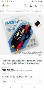
Hi, is there a change that i can put a highpass between the (aux) cable and amp. I need a highpass for my cheap subwoofer amp at 35 hz. I have seen some examples at parts express called the fmod subsonic filter but they are expensive because they have to be shipped from usa to europe. Can someone help me with this? Thanks!!
I assume you are meaning a passive line level crossover/filter? If so, link below might help.
https://www.t-linespeakers.org/tech/filters/passiveHLxo.html
https://www.t-linespeakers.org/tech/filters/passiveHLxo.html
I mean something like this but these are 50 euro for me ( wich is around 60 dollar )I assume you are meaning a passive line level crossover/filter? If so, link below might help.
https://www.t-linespeakers.org/tech/filters/passiveHLxo.html
Attachments
If you can install some RCAs in a small metal box, and a pair of series capacitors,
that is all that is needed for a high pass filter.
Or the high pass capacitors could even be installed inside the subwoofer,
in series right after the input jacks.
that is all that is needed for a high pass filter.
Or the high pass capacitors could even be installed inside the subwoofer,
in series right after the input jacks.

Thanks this is what i wanted to know but if it's this simple why don't people use this feature a lot more ? I see so many projects where the output is limited because of overexcursion at unusable frequencys.If you can install some RCAs in a small metal box, and a pair of capacitors,
that is all that is needed.
Or the capacitors could even be installed inside the subwoofer,
right after the input jacks.
So i just have to make a second order filter, split the positive wire ( i guess the same way as speakers ) and leave the negative wire intact. I have to do this for the right and left or am i thinking to complex about it?
Second order filters are much harder. They usually must have active circuitry.
A first order filter can just use a capacitor and the amplifier's input impedance for the R.
A first order filter can just use a capacitor and the amplifier's input impedance for the R.
Ok, a first order is much easier. What exactly do you mean with the amplifier impedance, my amplifier is 4ohm for the subwoofer and also 4ohm for the satelites.Second order filters are much harder. They usually must have active circuitry.
A first order filter just uses a capacitor and the amplifier input impedance for the R.
The sub amplifier has an input impedance, which should be something like 10k to 100k.
The capacitor goes in series with the signal before the sub amplifier (not after the sub amplifier).
The capacitor goes in series with the signal before the sub amplifier (not after the sub amplifier).
Second order filters are much harder.
Because it is passive it is droopy. If it is a high pass a significant input impedance of the power amp required to achieve anything reasonale has to be quite high.
Low pass just needs to have sufficient drive to not have the 2 series Rs cause level issues.
dave
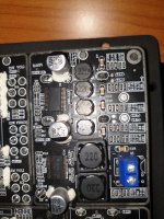
Right under you see the left and right coax unput with some resistance and rapacitorsThe sub amplifier has an input impedance, which should be something like 10k to 100k.
The capacitor goes in series with the signal before the sub amplifier (not after the sub amplifier).
Attachments
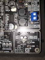
In this picture you can see the amplifiers for the satelites and subRight under you see the left and right coax unput with some resistance and rapacitors
Attachments
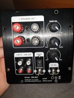
You don't want to mess with that at all.
For this sub amplifier, stay with outside capacitors.
But you'll need to know the amplifier's input impedance.
Also, why exactly do you need the high pass filter? Does the sub bottom out or distort?
For this sub amplifier, stay with outside capacitors.
But you'll need to know the amplifier's input impedance.
Also, why exactly do you need the high pass filter? Does the sub bottom out or distort?
Only an issue on the HP, in which case it is best to use the Rin as the shunt R in the (last) stage of the PLLXO.But you'll need to know the amplifier's input impedance.
dave
Thanks but i don't know how to find the amps inpedance! These are unknown brands, the only thing i know is that it uses a tpa3118 chip.You don't want to mess with that at all.
For this sub amplifier, stay with outside capacitors.
But you'll need to know the amplifier's input impedance.
Also, why exactly do you need the high pass filter? Does the sub bottom out or distort?
Yes the sub will botom out at lower frequencies, at 20 hz it will have an excursion of 20 mm, so i don't wanna play 20hz tones but 1 movie trailer with a low signal destroys the woofer while above 35 hz everything is within the xmax range.
Someone with more real world experience than me, but can you not just measure with a multimeter?
dave
dave
You need to measure the AC input impedance, and a simple multimeter will only measure the DC resistance. If there's an input DC blocking cap, the resistance will not be equal to the impedance. A simple way to do this measurement is to drive the amplifier input with a signal generator set to 100Hz through a resistor. Measure the level of 100Hz sent to the resistor and then the level at the junction of the resistor and the amplifier input (both relative to the amplifier input ground). If the measurement at the amplifier input is 1/2 of the generator level, then the series resistor is equal to the 100Hz impedance of the amplifier input. I used 100Hz since you have a subwoofer, and 100Hz should be in the passband. You also need to do this measurement with the amp on, so you do not want to use gargantuan signal levels - just enough to give a reliable AC voltage reading. So, select resistors until you find one that gives the 6dB level drop. You could use a potentiometer wired as a resistor to do this as well - adjust for 6dB level drop and then measure the series resistor.Someone with more real world experience than me, but can you not just measure with a multimeter?
Ok, find a 20k - 50k pot and connect the pot's wiper to one end terminal. This forms a variable resistor.Thanks but i don't know how to find the amps inpedance!
Connect this in series with the input signal to the amplifier.
Now input a constant 1kHz signal (sine etc.) and measure the amplifier output voltage.
At one extreme of the pot the signal will be at a maximum. Note this voltage value.
Now vary the pot until the output is 1/2 that maximum value. Disconnect the pot and measure it.
This will be the amplifier input impedance value to use for the HP filter.
- Home
- Source & Line
- Analog Line Level
- Diy highpass in aux cable