The idea of current drive amplifier based on no-NFB pentode topology seems pretty straightforward, however, there are some caveats that need to be addressed before embarking on such project. The common arguments against no-feedback pentodes are:
1. With no electric damping, boomy bass due to main speaker resonance.
2. Pentodes have higher distortion compared to triodes, therefore they need NFB to reduce it.
3. Pentodes have increased distortion with reactive loads, which most speaker's are.
4. Pentodes don't work well with output transformers, which benefit from low source impedance.
Is there anything else? Would be nice to see the complete list of problems before proceeding to how they can be addressed, mitigated or bypassed.
Add lower power supply rejection to the list of problems.
On the plus side, consider improved overlaod characteristics (RDH 4th ed p.563)

On the plus side, consider improved overlaod characteristics (RDH 4th ed p.563)
Pentode cathode follower circlotron using the second grid as DC-only servo bias? Although the plate resistance would probably sink the idea. Using a 1M6 and 0.22uF cap as a low pass filter would be easy enough to bring the servo bias down to near 1Hz - if you could wangle the NFB rules.
You could use a transformer-based circlotron?
Only other way is pre-shape the signal prior to amplification to cancel the noise.
Power supply noise - could you use bifolar windings and have bipolar design? Then use PS injection to cancel out the noise?
You could use a transformer-based circlotron?
Only other way is pre-shape the signal prior to amplification to cancel the noise.
Power supply noise - could you use bifolar windings and have bipolar design? Then use PS injection to cancel out the noise?
What do you mean by "current drive amplifier"?
No controlling negative feedback would be hard if you're attempting to maintain a current (or voltage) output?
A cheap and cheerful single ended pentode amp could be half of a basic experiment in current-driving a loudspeaker. Potential design desiderata (in no particular order) might include:
Measure and listen at 1 Watt in pentode mode, then UL, then triode?
- A quiet power supply;
- Output transformer suitable for a pentode (OK with higher rp, taps for UL)
- No NFB for high output impedance;
- Plenty of headroom - run the amp at lower levels for lower distortion, load it for optimum overload characteristics;
- Run a relatively sensitive speaker in a sealed, well-stuffed enclosure;
- Select a speaker with relatively low Qms (relatively high mechanical damping).
Measure and listen at 1 Watt in pentode mode, then UL, then triode?

Icsaszar: I followed your thread with great interest while it was active. What you discussed was the amplifier "with local feedback in each stage", which still belongs to the category of voltage drive amplifiers. Local feedback, such as Schade, UL, cathode, etc has been discussed extensively here during the last 20 years. What I want to discuss is pentode with no feedback of any kind, global or local, deliberately causing high output impedance.I opened a thread about a push pull amplifier without GNFB using 807 tubes. Use the search.
I experienced, measured, simulated and heard all that you described in post #1.
Eventually I applied GNFB and I am happy with it.
Bondini,
Your Post # 3 about power supply rejection.
. . . Remember, Post # 1 is for No output stage negative feedback.
That means the B+ ripple is a function of the plate impedance, rp; versus the output transformer primary Z.
Examples, start with a power supply B+ that has 100mV ripple, and a 5,000 to 8 Ohm output transformer.
5,000: 8 is a step-down ratio of 25:1
Triode:
A triode with plate impedance, rp = 1,666 Ohms.
100 mV ripple x ((5,000/(5,000 + 1,666) = 75 mV ripple across the primary, and 3mV ripple at the 8 Ohm tap.
. . . 3mV ripple to the speaker.
Pentode / Beam Power:
A pentode / beam power, with plate impedance, rp = 10,000 Ohms
100 mV ripple x ((5000/(5000 + 10,000) = 33mV ripple across the primary, and 1.33mV ripple at the 8 Ohm tap.
. . . 1.33nV ripple to the speaker.
Conclusion:
With no output stage negative feedback, the least ripple is from the pentode / beam power tube.
With no output stage negative feedback, the triode has more ripple.
I believe that what sser2 wants is an output amplifier stage that has high impedance (low damping factor).
If there is no feedback of any kind, the pentode / beam power modes have the highest output impedance.
A push pull pentode / beam power output, with no output stage feedback can have very low 2nd harmonic distortion, and
with certain output stage parameters can also have fairly low 3rd harmonic distortion too.
Just my opinions (and my experience with my first try of that unusual amplifier topology).
There was another very interesting medium long thread in the Tubes / Valve section about current drive amplifiers.
6A3summer explained well why the pentode output stage cant work well at lower frequencies due to limited inductance in the OPT.
There is other ways of obtaining high output impedance, some older amplifiers had the "variable damping factor".
There is other ways of obtaining high output impedance, some older amplifiers had the "variable damping factor".
At the output secondary, make a series connection of a current sensing resistor - between ground and the secondary common.
Connect the speaker across ground and the 4, 8, or 16 Ohm tap as appropriate.
Now, properly apply the voltage from the current sensing resistor to create a feedback loop that will make the output stage have a high impedance output.
Easier said than done, but that was done as early as the 1950s, and has been successfully used more recently by others, including Wavebourn.
One more time . . . Post # 1 was about a No feedback pentode output stage (high impedance = low damping factor).
Right?
Last edited:
With a no Fdbk pentode you get an output impedance (Rp) that varies as 1/Sqrt(current) and a forward gm that varies as 3/2 to 2 power law.
Class A P-P could clear some of that up. Another alternative would be Crazy Drive, pic below. Constant gm but still 1/Sqrt(I) Rp.
A 6V6 would get you 70K to 80K Ohm Rp. Could also use a cascode circuit to get high Rp, could be used with Crazy Drive too ( bottom tube ) for constant gm as well.

Class A P-P could clear some of that up. Another alternative would be Crazy Drive, pic below. Constant gm but still 1/Sqrt(I) Rp.
A 6V6 would get you 70K to 80K Ohm Rp. Could also use a cascode circuit to get high Rp, could be used with Crazy Drive too ( bottom tube ) for constant gm as well.
Last edited:
With any current amplifier one needs to move the damping to the loudspeaker, seen as a flattish impedance curve.1. With no electric damping, boomy bass due to main speaker resonance.
One has to be careful with XOs.
dave
Do you need more? 🙂Is there anything else? Would be nice to see the complete list of problems before proceeding to how they can be addressed, mitigated or bypassed.
Negative feedback cures all of the problems you listed.
Yes, sure - but then no current drive for you. Current drive reduces speaker-generated distortion, compared to voltage drive. That was the goal, not no-feedback pentode per se.Do you need more? 🙂
Negative feedback cures all of the problems you listed.
Yes - mechanical damping in the loudspeaker = flattish impedance curve = relatively high Rms = relatively low Qms (less than 2 would be good, can live with Qms=3 as per Pioneer B20FU20-51FW and other such drivers).With any current amplifier one needs to move the damping to the loudspeaker, seen as a flattish impedance curve.
One has to be careful with XOs.
dave
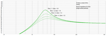
Low Qms plus a well-damped sealed enclosure helps control the "bass boom" that is otherwise the characteristic of current driving loudspeakers - the "boom" tends to swamp the audible/measurable advantages of current drive at higher frequencies. The "boom" is modeled below for a vented enclosure to exaggerate the effect and the tendency for lower Qms to reduce the "boom" when driven by an amplifier with an output impedance of 50 Ohm delivering 1 Watt (all other things being equal). The amp and the speaker can be designed to work together - synergistically as they say. 🙂
Attachments
I have to dwell on speakers for current drive at some length. I don' know - it may be inappropriate here, but if I post it on the Speaker forum, it will be sure ignored. But right speaker is paramount for the current drive issue. So, moderators, please forgive me.
Let us play a little game. Here are 3 field coil magnet drivers from the era before boxed speaker's and NFB. They are all 12", rated 5 to 20 W, same nominal impedance, have lightweight cones, and about same sensitivity. The black one has 1.5" diameter voice coil; the two others 1". You are building a "fullranger" speaker to match 5 W amplifier with low DF. Which one would you choose and why?
Assuming, it's not a WAW. Why not biamp; using the i-drive for the Wideband part crossed above its resonance, a more conventional high DF amp for the Woof?1. With no electric damping, boomy bass due to main speaker resonance.
I've read the bigger voice coil diameter has more "control" but I assume that's pushing against a high DF amp. So I'll choose the center one, because it's got the beefier field coil.Which one would you choose and why
I wonder, in the old consoles these came from, when played loudly; did the field coil make more magnetization, due to more current running through it - assuming of course it sits in series with the B+, in between two caps?
- Home
- Amplifiers
- Tubes / Valves
- No-feedback pentode amplifier