Already mentioned and addressed in #19, #20, #23 and #24...Are the caps in the wrong way around, + and - mixed up? That would explain it.
Are you sure they are not 10V caps - I saw a pic with '10V' on the top of one.
Jan
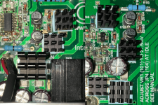
Caps are in the correct orientation. I double checked. They are SMD caps with a footprint that matches the PCB silkscreen.
The cap markings are misleading.They are Nichicon UCD 10uF 35 Volt caps I purchased from Mouser last year: Mouser:UCD1V100MCQ1GS.
I replaced the stock caps (circa 2006) which were also running hot.
The cap markings are misleading.They are Nichicon UCD 10uF 35 Volt caps I purchased from Mouser last year: Mouser:UCD1V100MCQ1GS.
I replaced the stock caps (circa 2006) which were also running hot.
Hook a scope up differential across the hot resistor should then give you the current. Then follow it.
I don’t have a scope at the moment. I will in the future when I get a scope.Hook a scope up differential across the hot resistor should then give you the current. Then follow it.
I don’t have a scope at the moment. I will in the future when I get a scope.
multi meter across it - it should give you a voltage, and V=IR so the V across it / R = current flowing through it. Then P=I*I*R, should then tell you if you're above 500mA or 1W etc whatever the parts are rated for.
AC impedance is a little more complex but so then is the measuring equipment required.
I just find a scope easier as you see any odd behaviour that may not show up on a MM with DC.
50 Volts, so 50V/2.2KOhms = .0227 Amps. P=.0227*.0227*2.2K = 1.135 Wats. These resistors are the factory stock ones. I've also found out the resistors in the right channel are in fact close to the electrolytic capacitors. Current summary, all 4 resistors are very hot and radiating heat through pcb to electrolytic caps. Perhaps installing a 2 -3 watt chip resistor would reduce heat, like this one. I noticed in the datasheet the resistor power rating falls with temperature rise. Will a higher power rated resistor (same size) run more efficiently and produce less heat? This one looks like it could work - Mouser: 35402K2JT.multi meter across it - it should give you a voltage, and V=IR so the V across it / R = current flowing through it. Then P=I*I*R, should then tell you if you're above 500mA or 1W etc whatever the parts are rated for.
AC impedance is a little more complex but so then is the measuring equipment required.
I just find a scope easier as you see any odd behaviour that may not show up on a MM with DC.
Attachments
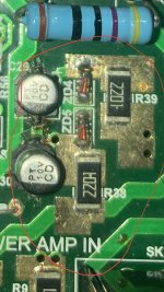
Those resistors (R38 & R39) have large PCB pads so I assume for heat dissipation/current. I would check to see if the 22mA seems like a reasonable value for the position it's in.
I ran a simulation on multisim.com without the opamps. That simulation showed 15mA. 22mA seems reasonable. It appears the circuit is working as designed with inadequate thermal management.Those resistors (R38 & R39) have large PCB pads so I assume for heat dissipation/current. I would check to see if the 22mA seems like a reasonable value for the position it's in.
Last edited:
I ran a simulation on multisim.com without the opamps. That simulation showed 15mA. 22mA seems reasonable. It appears the circuit is working as designed with inadequate thermal management.
105degC or 125degC caps would help in this instance then. It seems that some amp designers design for high temps (ie the op amps curves variation with temperature).
multisync at #12: "Are they too close to the dropping resistors and zeners? At 15 volts across the caps they would have to be leaking 10's of milliamps to get warm"
gghodg rules it out at #15: "The dropping resistors and zeners are not the source of heat."
.....everyone then started off brainstorming on all sorts of possibilities, including me silly enough to speculate 10V labeling on the cap was voltage rating, only to realize the "V" is code for 35V, and 10V reads 10uF/35V. That's an effective effort on the cap factory part in reducing carbon footprint, isn't it?
but soon after, at #25, gghodg backtracks: "Oh just checked the area next to the chip resistors and it’s really hot! Maybe it is the chip resistors (R38 and R39)after all." with double confirmation at #26, and #28, .............duh...
Nonetheless, problem identified! that's 90% job done. Victory!
Nah, not so fast, at #35, gghodg is seen rebutting himself: "Turns out it is not the resistors, or at least the resistors are not the main heat source and..."
WTH , LOL!🤣
Sorry, couldn't resist poking fun.🙂😉
Seriously, the 55V drop over 2k2 sounds a killer. Using copper plane on PCB as heatsink is not uncommon, but one has to observe certain constraints in design, such as maximum allowed temperature rise vs effective surface area for air contact, keeping out temperature sensitive components. Without forced air cooling, PCB heatsinking is not very effective given the poor thermal conductivity of the fiberglass-resin substrate, and usually only used when there is large PCB space that one can afford to throw away or temperature is allowed to get high, like 100C or even slightly higher.
Attached is part of a PCB design by me where a TO223 device is being passively cooled with PCB as heatsink. Note many vias are used to pass heat to the other side of the PCB where large exposed copper area presents. That design is estimated to dissipate 1.5-2W at 40C T-rise. The PCB has 2Oz copper.

In your case you probably have less than 55V over the 2k2 resistors? The bulk caps for the major rails are rated at 63V, I'd guess they would be operating at 58V or so. Take out 15V and there is 43V over the dropping resistor, making 0.84W heat each, two per channel, or 1.68W heat per heatsink. That is still a serious amount of heat to deal with. The PCB shown in the picture seems to have a lot less surface area than is needed, unless there are large exposed copper plane on the other side, but in that case I'd expect to see a lot of vias for thermal paths that I don't see. So I would not be surprised if the heatsink is operating a great T-rise than 40C, and that the heat finds its way along the copper foil/cladding to the nearby caps, and use their casing as extension of the heatsink.
There is this Panasonic cap at Mouser if you don't want to relocate the resistors.
Panasonic 25SVPD10M 2000hr@125C
The service life could be estimated by doubling the rated life per 10C lower operating temperature. Say the caps are cooked at 95C, with the 125C rated, the service life would be 16,000hours; it doubles again to 32,000 hours if the operating temp is actually 85C.
gghodg rules it out at #15: "The dropping resistors and zeners are not the source of heat."
.....everyone then started off brainstorming on all sorts of possibilities, including me silly enough to speculate 10V labeling on the cap was voltage rating, only to realize the "V" is code for 35V, and 10V reads 10uF/35V. That's an effective effort on the cap factory part in reducing carbon footprint, isn't it?
but soon after, at #25, gghodg backtracks: "Oh just checked the area next to the chip resistors and it’s really hot! Maybe it is the chip resistors (R38 and R39)after all." with double confirmation at #26, and #28, .............duh...
Nonetheless, problem identified! that's 90% job done. Victory!
Nah, not so fast, at #35, gghodg is seen rebutting himself: "Turns out it is not the resistors, or at least the resistors are not the main heat source and..."
WTH
, LOL!🤣Sorry, couldn't resist poking fun.🙂😉
Seriously, the 55V drop over 2k2 sounds a killer. Using copper plane on PCB as heatsink is not uncommon, but one has to observe certain constraints in design, such as maximum allowed temperature rise vs effective surface area for air contact, keeping out temperature sensitive components. Without forced air cooling, PCB heatsinking is not very effective given the poor thermal conductivity of the fiberglass-resin substrate, and usually only used when there is large PCB space that one can afford to throw away or temperature is allowed to get high, like 100C or even slightly higher.
Attached is part of a PCB design by me where a TO223 device is being passively cooled with PCB as heatsink. Note many vias are used to pass heat to the other side of the PCB where large exposed copper area presents. That design is estimated to dissipate 1.5-2W at 40C T-rise. The PCB has 2Oz copper.
In your case you probably have less than 55V over the 2k2 resistors? The bulk caps for the major rails are rated at 63V, I'd guess they would be operating at 58V or so. Take out 15V and there is 43V over the dropping resistor, making 0.84W heat each, two per channel, or 1.68W heat per heatsink. That is still a serious amount of heat to deal with. The PCB shown in the picture seems to have a lot less surface area than is needed, unless there are large exposed copper plane on the other side, but in that case I'd expect to see a lot of vias for thermal paths that I don't see. So I would not be surprised if the heatsink is operating a great T-rise than 40C, and that the heat finds its way along the copper foil/cladding to the nearby caps, and use their casing as extension of the heatsink.
There is this Panasonic cap at Mouser if you don't want to relocate the resistors.
Panasonic 25SVPD10M 2000hr@125C
The service life could be estimated by doubling the rated life per 10C lower operating temperature. Say the caps are cooked at 95C, with the 125C rated, the service life would be 16,000hours; it doubles again to 32,000 hours if the operating temp is actually 85C.
Attachments


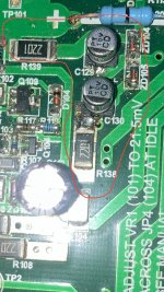
Correct 38V over the 2k2 resistors 🙂. Its a slow and meandering road sometimes to progress. Glad you were amused at my expense I guess. Seriously though. Thanks for the help. I'll look into the 25SVPD10M. FWIW all of the components worked without fail for the last 10 years before I replaced the electrolytics. There are a couple other hotspots (poor heatsinks for IRF9610) in this circuit that I have had to improve with diy. Photo attached of additional heatsink made from a 4X folded aluminum can. It works surprisingly well. The design is too dense, imo.multisync at #12: "Are they too close to the dropping resistors and zeners? At 15 volts across the caps they would have to be leaking 10's of milliamps to get warm"
gghodg rules it out at #15: "The dropping resistors and zeners are not the source of heat."
.....everyone then started off brainstorming on all sorts of possibilities, including me silly enough to speculate 10V labeling on the cap was voltage rating, only to realize the "V" is code for 35V, and 10V reads 10uF/35V. That's an effective effort on the cap factory part in reducing carbon footprint, isn't it?
but soon after, at #25, gghodg backtracks: "Oh just checked the area next to the chip resistors and it’s really hot! Maybe it is the chip resistors (R38 and R39)after all." with double confirmation at #26, and #28, .............duh...
Nonetheless, problem identified! that's 90% job done. Victory!
Nah, not so fast, at #35, gghodg is seen rebutting himself: "Turns out it is not the resistors, or at least the resistors are not the main heat source and..."
WTH
Sorry, couldn't resist poking fun.🙂😉
Seriously, the 55V drop over 2k2 sounds a killer. Using copper plane on PCB as heatsink is not uncommon, but one has to observe certain constraints in design, such as maximum allowed temperature rise vs effective surface area for air contact, keeping out temperature sensitive components. Without forced air cooling, PCB heatsinking is not very effective given the poor thermal conductivity of the fiberglass-resin substrate, and usually only used when there is large PCB space that one can afford to throw away or temperature is allowed to get high, like 100C or even slightly higher.
Attached is part of a PCB design by me where a TO223 device is being passively cooled with PCB as heatsink. Note many vias are used to pass heat to the other side of the PCB where large exposed copper area presents. That design is estimated to dissipate 1.5-2W at 40C T-rise. The PCB has 2Oz copper.
In your case you probably have less than 55V over the 2k2 resistors? The bulk caps for the major rails are rated at 63V, I'd guess they would be operating at 58V or so. Take out 15V and there is 43V over the dropping resistor, making 0.84W heat each, two per channel, or 1.68W heat per heatsink. That is still a serious amount of heat to deal with. The PCB shown in the picture seems to have a lot less surface area than is needed, unless there are large exposed copper plane on the other side, but in that case I'd expect to see a lot of vias for thermal paths that I don't see. So I would not be surprised if the heatsink is operating a great T-rise than 40C, and that the heat finds its way along the copper foil/cladding to the nearby caps, and use their casing as extension of the heatsink.
There is this Panasonic cap at Mouser if you don't want to relocate the resistors.
Panasonic 25SVPD10M 2000hr@125C
The service life could be estimated by doubling the rated life per 10C lower operating temperature. Say the caps are cooked at 95C, with the 125C rated, the service life would be 16,000hours; it doubles again to 32,000 hours if the operating temp is actually 85C.
Attachments
FWIW I found one solution using thermal pads and heat sinks. This setup works surprisingly well. The heatsink are too hot to the touch within a few minutes. I’m sure more surface area is needed but the heat sinks are alleviating some of the heat that radiates from the pcb to the capacitors.multisync at #12: "Are they too close to the dropping resistors and zeners? At 15 volts across the caps they would have to be leaking 10's of milliamps to get warm"
gghodg rules it out at #15: "The dropping resistors and zeners are not the source of heat."
.....everyone then started off brainstorming on all sorts of possibilities, including me silly enough to speculate 10V labeling on the cap was voltage rating, only to realize the "V" is code for 35V, and 10V reads 10uF/35V. That's an effective effort on the cap factory part in reducing carbon footprint, isn't it?
but soon after, at #25, gghodg backtracks: "Oh just checked the area next to the chip resistors and it’s really hot! Maybe it is the chip resistors (R38 and R39)after all." with double confirmation at #26, and #28, .............duh...
Nonetheless, problem identified! that's 90% job done. Victory!
Nah, not so fast, at #35, gghodg is seen rebutting himself: "Turns out it is not the resistors, or at least the resistors are not the main heat source and..."
WTH
Sorry, couldn't resist poking fun.🙂😉
Seriously, the 55V drop over 2k2 sounds a killer. Using copper plane on PCB as heatsink is not uncommon, but one has to observe certain constraints in design, such as maximum allowed temperature rise vs effective surface area for air contact, keeping out temperature sensitive components. Without forced air cooling, PCB heatsinking is not very effective given the poor thermal conductivity of the fiberglass-resin substrate, and usually only used when there is large PCB space that one can afford to throw away or temperature is allowed to get high, like 100C or even slightly higher.
Attached is part of a PCB design by me where a TO223 device is being passively cooled with PCB as heatsink. Note many vias are used to pass heat to the other side of the PCB where large exposed copper area presents. That design is estimated to dissipate 1.5-2W at 40C T-rise. The PCB has 2Oz copper.
In your case you probably have less than 55V over the 2k2 resistors? The bulk caps for the major rails are rated at 63V, I'd guess they would be operating at 58V or so. Take out 15V and there is 43V over the dropping resistor, making 0.84W heat each, two per channel, or 1.68W heat per heatsink. That is still a serious amount of heat to deal with. The PCB shown in the picture seems to have a lot less surface area than is needed, unless there are large exposed copper plane on the other side, but in that case I'd expect to see a lot of vias for thermal paths that I don't see. So I would not be surprised if the heatsink is operating a great T-rise than 40C, and that the heat finds its way along the copper foil/cladding to the nearby caps, and use their casing as extension of the heatsink.
There is this Panasonic cap at Mouser if you don't want to relocate the resistors.
Panasonic 25SVPD10M 2000hr@125C
The service life could be estimated by doubling the rated life per 10C lower operating temperature. Say the caps are cooked at 95C, with the 125C rated, the service life would be 16,000hours; it doubles again to 32,000 hours if the operating temp is actually 85C.
Attachments
Last edited:
That may work if capacitance isn’t critical.FWIW I found one solution using thermal pads and heat sinks. This setup works surprisingly well. The heatsink are too hot to the touch within a few minutes. I’m sure more surface area is needed but the heat sinks are alleviating some of the heat that radiates from the pcb to the capacitors.
Modern electronics likes cool which often points to a design problem if you’re needing to pump heat into the PCB rather than manage the heat generation to an external area (heatsinked).
How is capacitance involved when heatsinks are applied to the chip resistors, and electrically insulated by the thermal pads? The heatsinks are removing heat from the PCB, correct?That may work if capacitance isn’t critical.
Modern electronics likes cool which often points to a design problem if you’re needing to pump heat into the PCB rather than manage the heat generation to an external area (heatsinked).
The devices in which I had the same issue the issue was effectively solved by using a very small toroid of 5 or 7 VA 2 x 12 ...15V and a Graetz bridge and 2 x 2200 µF 35V caps. With LDO regs a 2 x 12V transformer is more than enough as output voltage is higher than 12V with such a low load.
This issue is simply because of cost cutting and possible not enough space (the latter being a showstopper). If you can add a small toroid or a small EI transformer preferably all on a PCB then the heat is gone. I used to have a "standard" PSU PCB to cure such issues.
Think of something like this and please note that you could do without the regulators or use the regulators instead of the Zener diodes:
http://www.pavouk.org/hw/dualpowersupply/en_index.html
These suggestions are taking away the root cause instead of sticking bandaids. Voltage dropping of such high values is simply asking for trouble and please think what will happen if one of the caps short circuits.....When no protection is used it is 2 burned woofers. What is more expensive?
Last edited:
How is capacitance involved when heatsinks are applied to the chip resistors, and electrically insulated by the thermal pads? The heatsinks are removing heat from the PCB, correct?
If you make a heatsink too large and it covers tracks, with the solder mask between you're asking for isolation and capacitance issues. The thermal pads themselves can act like a dielectric however you need a circuit that sensitive to capacitance for it to be a problem.
As said - the more you need to convert energy to heat the more the PCB heats and so increases noise etc etc.
I see, thanks for explaining this makes sense. I can't see if noise has increased. Would you recommend using soldering large THT resistors to the pads? At least that will move the heat source above the PCB.If you make a heatsink too large and it covers tracks, with the solder mask between you're asking for isolation and capacitance issues. The thermal pads themselves can act like a dielectric however you need a circuit that sensitive to capacitance for it to be a problem.
As said - the more you need to convert energy to heat the more the PCB heats and so increases noise etc etc.
Thanks, I don't know if I have the space to add this device. Would you recommend soldering THT resistors to the pads? At least the heat source would be above the PCB and closer to the vents.The devices in which I had the same issue the issue was effectively solved by using a very small toroid of 5 or 7 VA 2 x 12 ...15V and a Graetz bridge and 2 x 2200 µF 35V caps. With LDO regs a 2 x 12V transformer is more than enough as output voltage is higher than 12V with such a low load.
This issue is simply because of cost cutting and possible not enough space (the latter being a showstopper). If you can add a small toroid or a small EI transformer preferably all on a PCB then the heat is gone. I used to have a "standard" PSU PCB to cure such issues.
Think of something like this and please note that you could do without the regulators or use the regulators instead of the Zener diodes:
http://www.pavouk.org/hw/dualpowersupply/en_index.html
These suggestions are taking away the root cause instead of sticking bandaids. Voltage dropping of such high values is simply asking for trouble and please think what will happen if one of the caps short circuits.....When no protection is used it is 2 burned woofers. What is more expensive?
Ok, I see. Thanks for the link and information. What is the approximate size of the dual power supply you built? I might have space for that power supply on the input board. This amp does have circuit protection for when temperature or voltage boundaries are broken.Yes. Still a bandaid but any improvement is one.
What about just using the 15 vdc from the analog power supply on the input board?
But then why did the manufacturer design a dedicated power supply for the dc servo and current sensor circuits? Is a dual power supply necessary outside of protection mode issues? Sorry for all the questions, I am rather inexperienced in this area. I've attached the Input Board and Main Board schematics as reference. As it turns out the phono preamp also has it's own +/-15vdc power supply.
Attachments
Last edited:
- Home
- Amplifiers
- Solid State
- Using Aluminum Organic Polymer Capacitors in DC Servo Power Supply