I'm guessing there will be grounding issues using the analogue or phono preamp power supplies?Ok, I see. Thanks for the link and information. What is the approximate size of the dual power supply you built? I might have space for that power supply on the input board. This amp does have circuit protection for when temperature or voltage boundaries are broken.
What about just using the 15 vdc from the analog power supply on the input board?
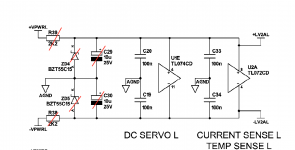
But then why did the manufacturer design a dedicated power supply for the dc servo and current sensor circuits? Is a dual power supply necessary outside of protection mode issues? Sorry for all the questions, I am rather inexperienced in this area. I've attached the Input Board and Main Board schematics as reference. As it turns out the phono preamp also has it's own +/-15vdc power supply.
That is a puzzling way of doing things. The amplifier indeed has way lower rails for the phono amplifier. That PSU uses separate windings as well. I can not think of why they chose to use the higher rails. Maybe to be sure the + and - go up and down simultaneously with the main rails ?! As it is done separately for each power amplifier channel that could be the reason. But... then there are the fuses in the power rails which are contradictory. A blowing fuse will cause the opamps to go to the rail voltage and therefor its function would be hampered.
Since I don't have the amplifier at hand I can not tell what to do but it seems connecting the +/- 15V to the phono board PSU is an obvious improvement. Too obvious as Creek would have done the same normally. There must have been a reason not to do so but which reason? The phono board PSU has no fuses and will be more reliable when one of the power amplifiers fuses would blow. IMO protection, current sensing and DC servo circuits should all be fully operational when a failure in the device occurs.
So an extra 5VA PSU would still be my solution just to be sure things work out OK with regards to power consumption power on/off ramping up/down etc.
Another bandaid solution is to have pre regulators for the 2k2 resistors dropping a part of the excess voltage so dividing the heat. This could be a small PCB per channel with relatively large through hole resistors and TO220 transistors. Not elegant, if it would be my device and if it is a good device I would go for the best solution which is not creating the heat in the first place.
When not then simply replace the caps for 125 degrees rated ones, sell it and build yourself a better constructed amplifier 🙂 I owned Creek devices but except for a nice tuner none of them stayed. When FM was under fire the tuner also went. Same goes for Perreaux, all nice looks but nothing special and (IMO) too many design imperfections.
Last edited:
Ha yeah I've already put so much time into this Creek amp, and have many fond memories listening to music on it. I'll probably keep it until it goes kaput. I didn't realize how jam packed (thermal management speaking) it was until repairing a Marantz PM-11S3, also class A/B at 100W but 2x the volume and 3x the weight! The Marantz sound was too laid back for my taste. Which integrated amp do you use? Anyway, FWIW The Creek phono preamp PCB is not factory stock and purchased separately. If I can manage to use a different power supply I didn't recognize that the second pair of chip resistors (R8/R9-R108/R109) (also with a 38 volts drop) in the left and right channel amp sections run just as hot! Thanks for the in depth explanations on the issue and solutions. If I do use a separate power supply for the dc servo section would I remove these resistors, zener diodes, and capacitors?That is a puzzling way of doing things. The amplifier indeed has way lower rails for the phono amplifier. That PSU uses separate windings as well. I can not think of why they chose to use the higher rails. Maybe to be sure the + and - go up and down simultaneously with the main rails ?! As it is done separately for each power amplifier channel that could be the reason. But... then there are the fuses in the power rails which are contradictory. A blowing fuse will cause the opamps to go to the rail voltage and therefor its function would be hampered.
Since I don't have the amplifier at hand I can not tell what to do but it seems connecting the +/- 15V to the phono board PSU is an obvious improvement. Too obvious as Creek would have done the same normally. There must have been a reason not to do so but which reason? The phono board PSU has no fuses and will be more reliable when one of the power amplifiers fuses would blow. IMO protection, current sensing and DC servo circuits should all be fully operational when a failure in the device occurs.
So an extra 5VA PSU would still be my solution just to be sure things work out OK with regards to power consumption power on/off ramping up/down etc.
Another bandaid solution is to have pre regulators for the 2k2 resistors dropping a part of the excess voltage so dividing the heat. This could be a small PCB per channel with relatively large through hole resistors and TO220 transistors. Not elegant, if it would be my device and if it is a good device I would go for the best solution which is not creating the heat in the first place.
When not then simply replace the caps for 125 degrees rated ones, sell it and build yourself a better constructed amplifier 🙂 I owned Creek devices but except for a nice tuner none of them stayed. When FM was under fire the tuner also went. Same goes for Perreaux, all nice looks but nothing special and (IMO) too many design imperfections.
Attachments
You should leave the caps (and they should be fresh/non overheated).
Idea: suppose you are a modern guy not bothering with record players. You could then disconnect the phono part and use the phono PSU for the amplifiers DC servo. Cheap and effective.
FWIW: After many discrete old fashioned amplifiers I mainly used various FDA but needed analog amplification because of an audioplayer with mediocre SPDIF output. It is a 2 x 4W class AB DIY chipamp with R-core transformer, ideal rectifier and a 22000 uF bulk cap. A semi DIY Merus MA12070 based transformer input amplifier is being assembled as we speak. No features, not more than 1 input, minimalistic.
Last edited:
Ok on the caps.You should leave the caps (and they should be fresh/non overheated).
Idea: suppose you are a modern guy not bothering with record players. You could then disconnect the phono part and use the phono PSU for the amplifiers DC servo. Cheap and effective.
FWIW: After many discrete old fashioned amplifiers I mainly used various FDA but needed analog amplification because of an audioplayer with mediocre SPDIF output. It is a 2 x 4W class AB DIY chipamp with R-core transformer, ideal rectifier and a 22000 uF bulk cap. A semi DIY Merus MA12070 based transformer input amplifier is being assembled as we speak. No features, not more than 1 input, minimalistic.
I still use vinyl. I try to buy it used when I can't find a digital copy or if I want to support an artist. I recently repaired a technics SL-1300, one of easiest to maintain fully-automatic Quartz locked turntable, imo.
What about using the analogue power supply, also +/- 15 VDC? As It turns out, I never use the Active preamp or Tape Out.
What is FDA? Nice, after learning more about how many few watts I typically need I plan to buy or try to build a lower wattage amp when this Creek goes kaput. Also thought about just using a battery powered active speaker with advances in battery technology.
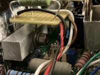
If relocate the resistors, perhaps use 3W fusible metal-oxide type, mount them on a perf board, secure the board on the power transistor mounting bolts, then run wires between the perf board and the main PCB. The current is small, thin wires like #26AWG would be a massive overkill. Twist up two wires to each resistor, then zip-tie the 4 pairs into sort of a harness to make it neat looking. This mod would completely take the heat away from the main PCB, and from the caps, at minimum alteration to the original setup both mechanically and electrically.
You may/may-not need to replace with longer mounting bolts for the power transistors.

You need to cut two slots to the perf board for it to ride on the mounting bolts.

If you don't feel like cutting the slots, perhaps use two crimp terminals instead, remove the plastic, flatten the butt-end, and solder them to the perf board.

You may/may-not need to replace with longer mounting bolts for the power transistors.
You need to cut two slots to the perf board for it to ride on the mounting bolts.
If you don't feel like cutting the slots, perhaps use two crimp terminals instead, remove the plastic, flatten the butt-end, and solder them to the perf board.
Thanks, I think for now I’m going to stick with the heatsinks mounted on the chip resistors and research alternate PSU. Why metal oxide vs wire wound resistors? The service manual calls for resistors with 1% tolerance and I haven’t found metal oxide resistors below 5% tolerance.If relocate the resistors, perhaps use 3W fusible metal-oxide type, mount them on a perf board, secure the board on the power transistor mounting bolts, then run wires between the perf board and the main PCB. The current is small, thin wires like #26AWG would be a massive overkill. Twist up two wires to each resistor, then zip-tie the 4 pairs into sort of a harness to make it neat looking. This mod would completely take the heat away from the main PCB, and from the caps, at minimum alteration to the original setup both mechanically and electrically.
You may/may-not need to replace with longer mounting bolts for the power transistors.
View attachment 1069025
You need to cut two slots to the perf board for it to ride on the mounting bolts.
View attachment 1069024
If you don't feel like cutting the slots, perhaps use two crimp terminals instead, remove the plastic, flatten the butt-end, and solder them to the perf board.
View attachment 1069026
Metal oxide film resistor is a lot less expensive and is designed to handle such duty, nothing is wrong with wire-wound resistors through for our particular application. 1% tolerance is not required for voltage dropping resistors. Service manual calls for whatever is used in the BOM of the design. In many cases 1% and 5% chip resistors virtually cost the same for large qty orders. The company where I work stocks 10s millions resistors, all 1% or better tolerance, not because required by designs, but for much less work load in management.
Ok I see. Thanks for the explanation and the design. Do you know why Creek chose chip resistors over THTs in the first place? I believe v.2 of this amp uses THT resistors. The 5350SE, the Destiny’s predecessor, also uses THT resistors. Your solution seems like a stable and inexpensive. The resistors would be directly beneath the heat vents which is great. No worries about if/when I move the amp. The current heatsinks are held down by gravity. Anyway, the thinner wires from the harness are also easier to solder on pads. One other thing that I remembered a user posted is that some heat is desirable in the PCB, e.g. the input transistors should ideally be the same temperature. I don’t know if there is any truth or theory to that statement. Regardless, I can always revert to the stock design at minimum cost. Ok I think I’m going to try your solution. Really appreciate the details.Metal oxide film resistor is a lot less expensive and is designed to handle such duty, nothing is wrong with wire-wound resistors through for our particular application. 1% tolerance is not required for voltage dropping resistors. Service manual calls for whatever is used in the BOM of the design. In many cases 1% and 5% chip resistors virtually cost the same for large qty orders. The company where I work stocks 10s millions resistors, all 1% or better tolerance, not because required by designs, but for much less work load in management.
Last edited:
I wasn't aware they had designs using THT before and after. That sounds to me like a failed attempt at replacing THT with SMD resistors for a more "green" looking, and saving a few pennies too -- SMD are always soldered by machine while THT are installed manually onto a PCB. I'd say they must have over estimated what the PCB could do as a heatsink. As far as "some heat is desirable in the PCB, e.g. the input transistors should ideally be the same temperature." goes, I'm not sure that is the case or by how much. The fact that subsequent design of this amp switched back to use THT indicates the folks at Creek wanted less temperatures in their PCBs.
To clarify I think the Destiny 2 used THT resistors for the DC Servo PSU. I found a photo of the interior but not the schematic. The Destiny Amp section is very much a clone of the 5350SE just with SMD components and more power. After looking more at the Destiny's schematic I stumbled on two 2k2 (rated at 1 Watt) resistors which are THT and dropping 33 volts. Creek used THT and SMD 2K2 resistors in the Destiny. I'm going to buy the metal oxide resistors and perf boards. I found some with drilled holes for mounting. I'll send photos. Thanks again for the help!
Last edited:
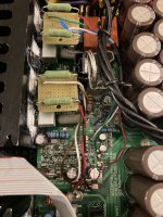
Thanks again for the help! I’ve also relaced surrounding components were replaced: Electrolytics, MLCCS, and diodes. A couple of the MLCC leads fell off while removing them. The excessive heat was wearing down components! The board is settling around 50C. Cool as cucumber.
Attachments
- Home
- Amplifiers
- Solid State
- Using Aluminum Organic Polymer Capacitors in DC Servo Power Supply