Hi All,
The current electrolytic capacitors in this DC servo power supply circuit seem to be running too hot around 85C. Will Aluminum Organic Polymer Capacitors run longer in this circuit by staying cooler?
https://www.mouser.com/datasheet/2/293/e_ucd-1795093.pdf
https://www.mouser.com/datasheet/2/420/PXGRA_e-2507364.pdf
The data sheets show the AOPCs have much lower ESR, much high ripple current rating, but they also have higher leakage current than the Aluminum Electrolytic Capacitors.
Does this necessarily mean they will run cooler in this application? How does a high leakage current play into things?
Attachments
I would probably use this: https://datasheet.lcsc.com/lcsc/2002201607_Ymin-VKMB1001E100MV_C487319.pdf
But I'm a fan of Ymin caps. They are excellent and cheaper than Western brands.
But I'm a fan of Ymin caps. They are excellent and cheaper than Western brands.
Thanks, but these have marginally better ripple current ratings than the current electrolytic. The cost of shipping is still even more than Aluminum Organic Polymer Capacitors.I would probably use this: https://datasheet.lcsc.com/lcsc/2002201607_Ymin-VKMB1001E100MV_C487319.pdf
But I'm a fan of Ymin caps. They are excellent and cheaper than Western brands.
5mm SMD. I probably looked at that capacitor. I'm working under the following assumption: Lower ripple current means higher temperatures, Aluminum Organic Polymer capacitors have much much higher ripple currents and therefore don't run as hot. The Panasonic would probably still run hot IMO.What is the size?
Panasonic makes a 125°C cap in 10ųF/25V.
The one I was talking about was Polymer but not 5mm.
This is the only 5mm cap that seems to fit your needs: https://www.mouser.ca/ProductDetail...G250ARA100ME46G?qs=FBI%2BX3tnPf1rNIsiMzw7TA==
This is the only 5mm cap that seems to fit your needs: https://www.mouser.ca/ProductDetail...G250ARA100ME46G?qs=FBI%2BX3tnPf1rNIsiMzw7TA==
Hi All,
The current electrolytic capacitors in this DC servo power supply circuit seem to be running too hot around 85C. Will Aluminum Organic Polymer Capacitors run longer in this circuit by staying cooler?
https://www.mouser.com/datasheet/2/293/e_ucd-1795093.pdf
https://www.mouser.com/datasheet/2/420/PXGRA_e-2507364.pdf
The data sheets show the AOPCs have much lower ESR, much high ripple current rating, but they also have higher leakage current than the Aluminum Electrolytic Capacitors.
Does this necessarily mean they will run cooler in this application? How does a high leakage current play into things?
I've used Panasonic AZA alu organics in a pre-amp stage power supply.
First thing is careful of the Vripple derating with frequency. The AZA, although specified as a 4000mA ripple current, has a severe derating of 0.10x for low frequency (ie where mains AC or low frequency sound exist). EDIT: the caps are EEH-AZA1E221B, EEH-AZA1J560B, EEH-AZS1E561B as I needed leaded radials.
For me this wasn't a problem with two 560uF 4000mA in parallel and 0.10 derating with a opamp consumption of ~12mA for each. The resulting parallel ESR is 5mOhm. The op amps are slow at 7V/uS and 16MHz bandwidth so worthy checking out vs your intended use.
The amp sounds fine and detailed.
Yes, I see now the last one I linked is 0.05 at 120Hz... meaning 1300mA of ripple at 100kHz+ but only 65mA at 120Hz.
Ok, I can’t find ripple current data below 100KHz in the datasheet for the alu organics I linked to in my post. These opamps tl072cdr and tl074cdr have a 20V/uS slew rate. Might there be a problem with the alu organics in series? It seems there are a lot of unknowns here. Thanks for the info.I've used Panasonic AZA alu organics in a pre-amp stage power supply.
First thing is careful of the Vripple derating with frequency. The AZA, although specified as a 4000mA ripple current, has a severe derating of 0.10x for low frequency (ie where mains AC or low frequency sound exist). EDIT: the caps are EEH-AZA1E221B, EEH-AZA1J560B, EEH-AZS1E561B as I needed leaded radials.
For me this wasn't a problem with two 560uF 4000mA in parallel and 0.10 derating with a opamp consumption of ~12mA for each. The resulting parallel ESR is 5mOhm. The op amps are slow at 7V/uS and 16MHz bandwidth so worthy checking out vs your intended use.
The amp sounds fine and detailed.
Thanks but those are the same caps I linked to in my post 🙂The one I was talking about was Polymer but not 5mm.
This is the only 5mm cap that seems to fit your needs: https://www.mouser.ca/ProductDetail/United-Chemi-Con/APXG250ARA100ME46G?qs=FBI%2BX3tnPf1rNIsiMzw7TA==
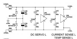
Maybe I am missing something. Why would C29 and C30 get hot? They are for a couple of opamps and shouldnt get even warm. Are they too close to the dropping resistors and zeners? At 15 volts across the caps they would have to be leaking 10's of milliamps to get warm

Ok, I can’t find ripple current data below 100KHz in the datasheet for the alu organics I linked to in my post. These opamps tl072cdr and tl074cdr have a 20V/uS slew rate. Might there be a problem with the alu organics in series? It seems there are a lot of unknowns here. Thanks for the info.
TL072CDR is 2.5mA max supply current. However it also depends on the input ripple how long the main supply takes to feed. If it's only providing 65mA that may be enough if it's only feeding the opamp.
I don't think the opamp's requirements are going to cause a problem, but what is the PS also powering and what is the input power look like?
Maybe I am missing something. Why would C29 and C30 get hot? They are for a couple of opamps and shouldnt get even warm. Are they too close to the dropping resistors and zeners? At 15 volts across the caps they would have to be leaking 10's of milliamps to get warm
Good point - warm caps seem to indicate they're really working hard (why?) or they're turning into resistors (leak and failing). Are there any hot resistors or transistors around indicating a shorting failure?
The dropping resistors and zeners are not the source of heat.Maybe I am missing something. Why would C29 and C30 get hot? They are for a couple of opamps and shouldnt get even warm. Are they too close to the dropping resistors and zeners? At 15 volts across the caps they would have to be leaking 10's of milliamps to get warm
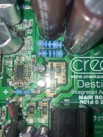
The amp is dual mono. There are two dc servo circuits with total of 4 of these electrolytic capacitors (C29,C30,C129,C130). All of these caps are running hot. This appears to be by design. The diodes and resistors are not the heat source and not in close proximity to the capacitors. I recently replaced the stock caps (10 years old - also hot) with the Nichicon UCD series thinking lower ESR would improve things. VPWR is +\-50 volts, LV2A is +\- 15 volts. Here’s the complete circuit for the amp section, and photo of the caps, diodes, resistors, and tl74cdr there on the left. I should also mention the MLCCs (C19/20) are also hot. Could this be inefficient design then. I’m not seeing obvious shorting. Perhaps these aren’t too hot and should be ok for several years?Good point - warm caps seem to indicate they're really working hard (why?) or they're turning into resistors (leak and failing). Are there any hot resistors or transistors around indicating a shorting failure?
Attachments
Last edited:
Hmm hot caps indicate heavy current draw (or bad input ripple).
I see (page 5) that the servo power supply also provides current to the power amp sense too.
I'd be tempted to check the caps for capacitance and the components through that path.
I see (page 5) that the servo power supply also provides current to the power amp sense too.
I'd be tempted to check the caps for capacitance and the components through that path.
Ok I will do that. The only components I haven’t replaced are c33 and c34. Perhaps those are out of spec in both circuits? I might have spare 100nF caps to replace c33/34. Thanks I’ll check on this.Hmm hot caps indicate heavy current draw (or bad input ripple).
I see (page 5) that the servo power supply also provides current to the power amp sense too.
I'd be tempted to check the caps for capacitance and the components through that path.
Hmm hot caps indicate heavy current draw (or bad input ripple).
I have not examined the circuit but assuming very low current draw my guess is is either the caps are defective/leaking, or they are getting heated through the pcb pads from something else. Ripple is a remote possibility.
I wish it were that easy 🙂 Why would the manufacturer print the voltage and not the capacitance on the capacitor? Those caps are 10uF, and actually rated at 35Volts.Mouser:UCD1V100MCQ1GSfrom the PCB assy picture you seem to have 10V rated caps on 15V rails.....and if that turns out to be the case, the caps would not like it.View attachment 1057846
Last edited:
- Home
- Amplifiers
- Solid State
- Using Aluminum Organic Polymer Capacitors in DC Servo Power Supply