No, no and once again no. Sorry that my energy is ending with you.So we are talking about a very small frequency band were issues might occur.
That section is determined by the Q-factor of the system, with mostly a difference between 0.5 and 0.707.
That difference is quite small.
My apologies for not doing it in your program.
But for quick theoretical studies, I just find this other program much easier to work with.
Anyway, so since GD is by definition connected with the frequency response = Q-factor as well as amount of energy around Fb.
This means there will be a difference in response.
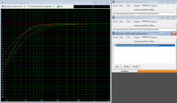
I have just attached some random system (not important, just first one in line).
In this case the total system response is corrected with a Linkwitz-Transform.
A perfect tool to investigate certain scenario's.
In this case you can see how the GD is connected to the response of the system.
You can also clearly see how little the difference is in GD, but how much bigger the difference is in the frequency response.
But for quick theoretical studies, I just find this other program much easier to work with.
Anyway, so since GD is by definition connected with the frequency response = Q-factor as well as amount of energy around Fb.
This means there will be a difference in response.
I have just attached some random system (not important, just first one in line).
In this case the total system response is corrected with a Linkwitz-Transform.
A perfect tool to investigate certain scenario's.
In this case you can see how the GD is connected to the response of the system.
You can also clearly see how little the difference is in GD, but how much bigger the difference is in the frequency response.
Attachments

Sorry to hear that, but I also don't see much contributions back.No, no and once again no. Sorry that my energy is ending with you.
So if one says "no" in a discussion, it is usually common sense also to explain the "no" with arguments.
In this case I am explaining very basic control theory, so I find it rather strange to hear a "no" on that part.
Well that is how science works.One more thing about "Toole et al". Those ex Harman fellows are continuously writing/talking about statistical preference of "people". Loyal followers quote their texts just like it would or should be valid for everyone. Talking about generalized preference is primarily general info and for manufactures trying to make universal and conventional products for majority. Higher goals and advanced - or just different speaker concepts are certainly allowed for any manufacturer and listener. As an individual with own ears and brain I find filtered preference very close to insult. Especially if someone on discussion forum starts to claim that some feature is insignificant or no one cannot hear or feel it. That is arrogant BS. We really do not have to have the same hearing capabilities and preferences neither in DIY nor commercial audio.
Science is by definition statistics.
Meaning you can only tell something with a certain certainty.
I don't see that "conventional products for majority" in his books at all, mostly because he is referring to papers that don't care about those things at all.
Therefor, as I said before, context is always key.
But if I am reading that even a bunch of trained experts, musicians and audio engineers are having trouble hearing something in an highly controlled test.
I don't know, but I find it very unlikely that it can be very audible in a practical environment.
Of course there are always exceptions, for you to decide if you're an exceptional listener or not.
Or maybe you don't believe it that's also fine, there is literally not standing anything in your way to prove the world something else.
Matter of doing some experiments, writing a report and send it to the well known acoustic organizations.
I think the majority is more than happy to see a different perspective on things.
I agree with you that people shouldn't just omit personal taste, preference and believes on such a strong way.
Last edited:
Actually, I was just reading a bit further during a (very late) lunch break just for fun.
(seeing what's different in the new edition)
But even Toole is very aware of the fact that you can't always predict everything
"The only meaningful target for conventional distortion metrics is “zero.” Above that, somebody, sometime, listening to something, may be aware of distortion, but we cannot define it in advance.
A recent listening test proved its worth when it revealed that a loudspeaker having excellent looking spinorama data (Section 5.3), which normally is sufficient to describe sound quality, was not rated highly as expected. The problem was found to be inter-modulation distortion, an extremely rare event, associated with the way sounds from a woofer and tweeter combined in a concentric arrangement—so constant vigilance and listening are essential."
Thanks DcibelHi Navin,
I hope that you have plans to acquire measurement gear, using manufacturer data has its limits in accuracy and reliability, and especially so for drivers aimed 90 degree to the listener. My recommendation for this type of simulation would be for familiarization of the tools, final design work of a speaker that you intent to enjoy for years to come should be completed with real measured data.
WinISD is not needed, VituixCAD includes a perfectly well functioning enclosure modelling tool.
The "export" buttons is what you are looking for in the Diffraction and enclosure tools to save response data. VXE/VXB files contain only the program settings, not the response result.
I've attached a document that I wrote a while back to help you generate response files using manufacturer data. Please read the first page to understand the limitations of following this process.
Yes, I do plan to get a testing kit (see link) once I have selected the drivers. I am using Vituix Cad only to ensure I have selected the correct combination of drivers. This kit is available locally (India).
https://diyaudiocart.com/tools-and-...ter-Based-Speaker-Audio-Component-test-System
I used the Freq vs SPL response of the MAOP 7 and a 200mm x 1400mm baffle to get a simulated response of the MAOP 7 on the baffle. This is saved as the Closed Full Space response.
I then used the Enclosure tool to get the following:
Seas L18RNX-P TotalSPL4pi.txt
Seas L18RNX-P Impedance.txt
This response however does not account for the response of the driver. It's an ideal response of the driver in a box based on only the T/S specs of the driver and box and port dimensions.
I am trying to use the merge tool to merge the FRD and ZMA curves of the driver with the Enclosure response. And also the effect of the crossover on the driver in the box.
How do I merge the FRD and ZMA curve of the driver with the Enclosure response?
Once I am able to merge the FRD and ZMA curves of the driver with the enclosure response, how would I export this curve so it can be used for the crossover design section of the program?
Thanks.
I've tried to learn to read ETC for some ten yes so far... poor success.Fortunately yes, though nowadays we have better tools to control timing than few decades ago. For example, this is basically the same speaker as passive and active. Not exactly the same box but quite alike (passive had better shape acoustically).
View attachment 1057088
More material.I've tried to learn to read ETC for some ten yes so far... poor success.
This is well-timed system. There is some diffraction because no waveguide and edge roundings are not maximal. ETC drops very fast with help of linear phase XO. Strong piano and percussion also with low SPL. Soundstage is okay, though would be better with stronger directivity or less diffraction.
This is probably the worst timing I have met IRL. ETC drops very slowly due to IIR XO with steep slopes. Very weak piano and percussion with any SPL, and soundstage scattered despite of large waveguide.
Excess group delay is easier to read but it does not reveal acoustical problems such as early reflections from stand and baffle/box so well.

Member
Joined 2003
You were given a nice instructional document above.How do I merge the FRD and ZMA curve of the driver with the Enclosure response?
Once I am able to merge the FRD and ZMA curves of the driver with the enclosure response, how would I export this curve so it can be used for the crossover design section of the program?
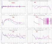
Here same speaker, same dsp settings (all-LR2, IIR, 4-way) measured indoors in same room at 1,5m vs. spot (2,5+table between speaker and mic). Every differences you see come from environment! 12ms gating and 1/3 smoothing. 0,1ms smoothing for ETC
This is why measurement conditions are so important!
This is why measurement conditions are so important!
Attachments
I'm fully aware that good experiences around the world with speakers having minimum phase response or transient perfect XO can be just coincidences though possibility is suspiciously high to be just an accident. I don't even mind small excess group delay because it's possible to design dynamic, accurate and presence sound without extreme accuracy in timing. It's just one possible tool which should not be totally ignored to avoid creating average or lame gear, and ranking it to top-3 by spinorama for example on ASR.But if I am reading that even a bunch of trained experts, musicians and audio engineers are having trouble hearing something in an highly controlled test.
I don't know, but I find it very unlikely that it can be very audible in a practical environment.
Toole's comment about distortion suits very nicely also for timing:
The only meaningful target for excess group delay is “zero.” Above that, somebody, sometime, listening to something, may be aware of it, but we cannot define it in advance.
I was not talking about normal group delay due to high pass slope of system response. Of course sealed and front/back -symmetrical dipole have some benefit over reflex because they don't produce excess group delay as LF radiator, but significant differences for example in hammer hit exist also with vented speakers, and bass extension does not matter (much). Excess group delay matters, and that is created with steep (symmetrical) IIR crossover especially at low mid which increases delay at upper bass ... low mid where fundamental frequencies of many instruments exist.In this case you can see how the GD is connected to the response of the system.
Also early reflections don't matter much because peak pressure of transient increases very fast after hammer hits the membrane or string. Whole band adds up to pressure peak quite instantly, changes to fundamental and decays down.
Let me try doing it step by step again from scratch.You were given a nice instructional document above.
Just to be sure, I have to do this twice, once for each driver right?
The cabinet baffle for the MAOP 7 would be 1400m x 200mm so that part is understood. However, the L18RNX are in push-push there would be no baffle step for the woofers. So how do I modify steps 3 and 4 in your instructions for this?
Yes that's what we have been talking about the whole time?I was not talking about normal group delay due to high pass slope of system response. Of course sealed and front/back -symmetrical dipole have some benefit over reflex because they don't produce excess group delay as LF radiator, but significant differences for example in hammer hit exist also with vented speakers, and bass extension does not matter (much). Excess group delay matters, and that is created with steep (symmetrical) IIR crossover especially at low mid which increases delay at upper bass ... low mid where fundamental frequencies of many instruments exist.
Also early reflections don't matter much because peak pressure of transient increases very fast after hammer hits the membrane or string. Whole band adds up to pressure peak quite instantly, changes to fundamental and decays down.
In case of the previous pictures Genelec, it's obviously the (steep) lowpass filter for the woofer.
We can even determine the crossover frequency as well as the filter order from it.
I was just about to show that actually.
The normal group delay is still relevant, in the sense that when the excess group delay is in the same order of magnitude, there isn't much difference.
You're probably right about the early reflections, but the other reflections as well as standing waves still exist.
That's why I have still my doubts how audible it is.
The problem only exist for steep filters around 200-500Hz.
Which again is a very limited frequency range. Only being used in 3-way systems or FAST systems.
Filtering above those frequencies and the GD will be very small
Generally speaking, these kind of systems are pretty new in the commercial world.
(already been used for at least 10-15 years in DIY world).
Or active systems to begin with if we talk about home hifi
(for some reason people like to still use less linear passive filters)
Which maybe give a bit of an answer why it's not really been talked about in Toole's book.
He (with him many others) is mainly focused on what is commercially available.
Very different world than the DIY world. Were people often try lots of things.
It reads like you think he/they do this on purpose, but I think it's just them being a little naive on this particular use case.
As I already mentioned before, there are plenty of other details missing in his book (especially the 1st edition)
I understand the discussion is about how audible it is.
But practically speaking it's pretty easy to fix by using FIR filters (IIR can be used for the other filters even) or by delaying the other speakers. Which already has been said.
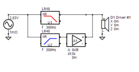
The reason why I'm repeating it, is because it gives us an opportunity to do some ABX testing.
Because it's just a case of making two identical filters in VCAD and put in in a DSP or EQ_APO or what have you and switch between the two.
In fact, it can be even done with the same setup, and by just adding this litter filter construction.(see attachment).
In this case we could even just apply this to some music snippets so people can test it (blind) on speakers as well as on headphones. We can use some VST filters or so for that (I use Ardour for recording my instruments, so will have a look)
Attachments
Which brings me to something about VCAD.
When using the GD/phase graph, I noticed that as soon as some traces or filter block are removed/added, the graph goes back to the default state.
Which can be very frustrating when one doesn't need certain traces at all and manually have to disable them again and again.
Feels very counter intuitive.
Member
Joined 2003
"no baffle step" is certainly a misnomer. In any case, the process in steps 3 and 4 does not change. When adding the drivers to the crossover section, just enter X,y,z, rotation and tilt values accordingly.Let me try doing it step by step again from scratch.
Just to be sure, I have to do this twice, once for each driver right?
The cabinet baffle for the MAOP 7 would be 1400m x 200mm so that part is understood. However, the L18RNX are in push-push there would be no baffle step for the woofers. So how do I modify steps 3 and 4 in your instructions for this?
If you're talking about driver traces, visibility is controlled by driver instance in XO schematic. 'Hide traces' in context menu or H button below schematic image.When using the GD/phase graph, I noticed that as soon as some traces or filter block are removed/added, the graph goes back to the default state.
Traces window is global service for all charts in all tools. It cannot make permanent changes to traces related to components which are created every time when e.g. crossover network is parsed.
Yes, I already know that this can be done by selecting hide traces from the driver itself.If you're talking about driver traces, visibility is controlled by driver instance in XO schematic. 'Hide traces' in context menu or H button below schematic image.
Traces window is global service for all charts in all tools. It cannot make permanent changes to traces related to components which are created every time when e.g. crossover network is parsed.
It's just that other graphs don't have these issues, it just doesn't makes any sense that when the user selects to hide traces in the graph they will show up again (and have to figure out it's overruled by the drive setting)
This is also only with the phaswe/GD graph, all the other graphs don't have this issue, so it feels very inconsistent.
I would consider something else than side woofers. For example WWCWW - just like Kef R11. With side woofers directivity index drops to zero or slightly negative. Baffle step exists to 90 deg, but not to 0 deg and 180 deg. Solution is slightly worse than normal (R11) and significantly worse than actual half space design i.e. flush-mounted wall speaker producing direct power about twice.The cabinet baffle for the MAOP 7 would be 1400m x 200mm so that part is understood. However, the L18RNX are in push-push there would be no baffle step for the woofers. So how do I modify steps 3 and 4 in your instructions for this?
I was just following the expert advice I received here."no baffle step" is certainly a misnomer. In any case, the process in steps 3 and 4 does not change. When adding the drivers to the crossover section, just enter X,y,z, rotation and tilt values accordingly.
https://www.diyaudio.com/community/...mpensation-methods.230342/page-4#post-6908230
Sorry for the cross-post. A KEF Blade Clone using WAW is being discussed here
https://www.diyaudio.com/community/threads/new-markaudio-drivers.324962/page-104
- Home
- Design & Build
- Software Tools
- VituixCAD