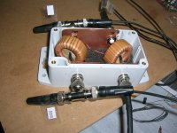
Took a while, but I finally made a cable with jumper-selectable impedance.
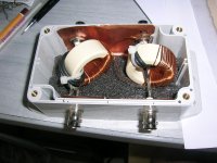
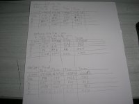
On the base of Sommer cable SC260 (2*5m, 2*6mm²) I calculated the networks for 2, 4, 6, 8 and 10Ohm speakers (some values between are also possible).
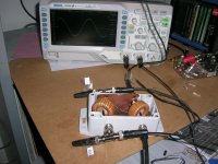
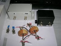
I then made boards for it and put 3 of them on each side in small boxes equally distributed over the length of the cable.
Speakers are OSMC, with a somewhat uneven imepedance characteristic around 8Ohm. Here are my impressions...
First I heard to the music for a couple of hours without any jumpers installed, thus, the cable as is.
It was like there is some kind of curtain in front of the music, which superimposes some grainynes/noise. Soundstage is also slightly limited.
Then I jumpered the cable for 8Ohm speaker impedance. The curtain dropped instantly and the sound was clear as one could wish for. Instruments were sharply focussed and soundstage and dynamics improved notablely.
A couple of days and many records later I became curious if/hoiw the other impedance-settings might imfluence the sound:
First I added one capacitor via jumper, which changed the impedance only slightly from 8,0 to 8,3Ohm. I cannot exactly tell if there was a noteable difference, maybe the instruments achieved a tiny bit more focus (probably expectation bias, probably not) ...
Next I put the jumpers to 6Ohm: treble fully out of control! Was it oscillations, resonances, idk. I switched of the music immediately.
Next 10Ohm: better again, but still something seemed not quite as right as the 8Ohm version.
I then went back to 8,3 Ohm setting for good and I'm very pleased with this cable.
I don't want to take any conclusions out of this, as it was all my subjective impression and I did not make any measurements.
Still I wonder what happened when I switched to a cable impedance lower then the speaker impedance. Is this behavior explainable, probably prdictable?
If so: Hans mesaured his MIT cable to 8Ohm. Could the same happen if one connects it to a 10Ohm speaker?
Cheers, Boris
On the base of Sommer cable SC260 (2*5m, 2*6mm²) I calculated the networks for 2, 4, 6, 8 and 10Ohm speakers (some values between are also possible).
I then made boards for it and put 3 of them on each side in small boxes equally distributed over the length of the cable.
Speakers are OSMC, with a somewhat uneven imepedance characteristic around 8Ohm. Here are my impressions...
First I heard to the music for a couple of hours without any jumpers installed, thus, the cable as is.
It was like there is some kind of curtain in front of the music, which superimposes some grainynes/noise. Soundstage is also slightly limited.
Then I jumpered the cable for 8Ohm speaker impedance. The curtain dropped instantly and the sound was clear as one could wish for. Instruments were sharply focussed and soundstage and dynamics improved notablely.
A couple of days and many records later I became curious if/hoiw the other impedance-settings might imfluence the sound:
First I added one capacitor via jumper, which changed the impedance only slightly from 8,0 to 8,3Ohm. I cannot exactly tell if there was a noteable difference, maybe the instruments achieved a tiny bit more focus (probably expectation bias, probably not) ...
Next I put the jumpers to 6Ohm: treble fully out of control! Was it oscillations, resonances, idk. I switched of the music immediately.
Next 10Ohm: better again, but still something seemed not quite as right as the 8Ohm version.
I then went back to 8,3 Ohm setting for good and I'm very pleased with this cable.
I don't want to take any conclusions out of this, as it was all my subjective impression and I did not make any measurements.
Still I wonder what happened when I switched to a cable impedance lower then the speaker impedance. Is this behavior explainable, probably prdictable?
If so: Hans mesaured his MIT cable to 8Ohm. Could the same happen if one connects it to a 10Ohm speaker?
Cheers, Boris

You basically added another crossover prior to speaker's passive crossover.I then made boards for it and put 3 of them on each side in small boxes equally distributed over the length of the cable.
Bravo! I need to dig up those TAS magazines. I got them in a few boxes.That cable looks like one Enid Lumley (RIP) did decades ago.
It's not a crossover but an impedance-correctionYou basically added another crossover prior to speaker's passive crossover.
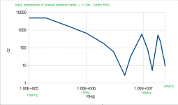
That cable impedance is the Radio Frequency Characteristic Impedance. For speaker cables, its value doesn't come into play until frequencies approach 1 Megahertz.
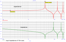
Some amplifiers get easily unstable with long speaker cables that are terminated by mostly inductive load at HF. Zobel termination helps to cure this issue. Speaker cable impedance is violent at HF above 1MHz, with capacitive dips in uF. Especially if the cable has coaxial structure. I have measurements to support my claims.
What wrong is there for speaker cables that needs correction?That cable impedance is the Radio Frequency Characteristic Impedance. For speaker cables, its value doesn't come into play until frequencies approach 1 Megahertz.
Nothing new.By the way, we have been through all this stuff before.
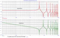
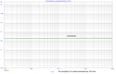
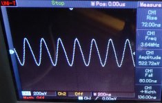
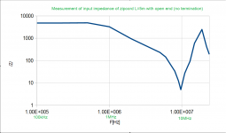
Not sure guys that you understand the issue. Let me speak by plots. It is a simulation of impedance of 7m speaker cable, open end, resistor terminated with matched impedance, terminated with unmatched impedance. And also a screen shot of oscillating amplifier with the real cable. The way to stop oscillations is to terminate the cable. It should be understood that the cable is not a mere combination of inductance, capacitance and resistance, when we consider what the real amp sees.
Attachments

More on cables ..
Audio seems to be the one place were we don't pay attention to impedance matching the interface. In RF, video, etc... we use 50 or 75 ohms and terminate the receiver side accordingly.
If you have ever measured transmission lines, you quickly understand why impedance matching is so important.
Unfortunately, many people think they know better and such things are impossible. They measure the audio band using sine and square waves and forget about the rest.... the Julian Hirsch philosophy.
BTW- one thing I didn't see in your testing is using amplifiers with different output impedances. I got some Class D amps with extremely low output impedances and their damping factor must be heard to be believed: the tightest, fastest (*) bass you can imagine.
(*) Yeah, just tickling the audioNotScienceReview crowd.... "fast bass".. ;-D
What I didn't see is the listening test, unless I missed it.BTW- one thing I didn't see in your testing is using amplifiers with different output impedances.
 I bring it up because this is audio.
What I didn't see is the listening test, unless I missed it.
Did you read the paper he pointed to? He blew the amp....
No listening for you!
Last edited:
BTW- one thing I didn't see in your testing is using amplifiers with different output impedances. I got some Class D amps with extremely low output impedances and their damping factor must be heard to be believed: the tightest, fastest (*) bass you can imagine.
Hi Tony, I have given myself a break at DIYaudio in the past years and the effect of amplifier output impedance (and cable impedance) that I measured I posted at ASR. Yes class D amps are usually very good at low frequencies, but the class D amps based on hysteresis switching with output LC filter out of the FB loop have inevitably the FR modulated by speaker complex impedance, this may start as soon as above 5kHz if the impedance has capacitive characteristic there. Not speaking about peaking with higher R load, of course. Phase lead compensation based circuits with FB only behind the LC filter like NCore and Purifi do not suffer from this issue. It is also still possible to get extremely low frequency independent output impedance with well designed class A amplifiers that do not suffer from Gm doubling and output stage crossover/switching.
Last edited:
I have noted with my Acoustic Reality ICE amps, driving Magnepans (4 ohms), vintage ADS L810s (4 ohms) and Acoustic Energy AE1s (16 ohms) that the bass is very tight but the treble is soft. In those L810s, the bass must be heard to be believed!
I haven't had a chance to try the NCore and Purifi into my speakers, but I have an NC252MP eval board sitting on my desk which I plan to build out. We'll see how that one works. I keep looking at the Purifi eval boards as I've been told they are most excellent.
Speaking of Class A amps, I have driven my DIY A5 monos and F5 monos and they have very smooth treble and very good bass as well. But then, I tried a CJ MF2100 and it drove the Maggies extremely well too.. so did a NuForce STA200, except that one ran very hot into the Maggies, but did an explendid job into the AE1s. Cables are Kimber 4TC and 8TC. I have not tried other cables with those speakers.
I suppose the 16 ohm loads are rather benign and the Kimber TC cables rather "normal" in their capacitance.
I do wonder, though, if a stout power supply can overcome the power implications of oscillations into a reactive load even given a highish output impedance. Meaning that a power supply that can push lots of current through might be more impervious to very low impedance loads and reflections due to mistmatching. For example, I have my Audio Research D70 amp wired to drive the 16 ohm and ground transformer taps via an extra set of banana jacks. It still can drive low impedance speakers quite well, with the Kimber cables. It can't drive the Maggies very loud, but that's a tube current issue to the speakers... internally that power supply is a beast.
My 12 cents to NC252MPI haven't had a chance to try the NCore and Purifi into my speakers, but I have an NC252MP eval board sitting on my desk which I plan to build out. We'll see how that one works. I keep looking at the Purifi eval boards as I've been told they are most excellent.
https://pmacura.cz/pma_nc252mp.htm
and to class A
https://pmacura.cz/pma4_en.htm
Re oscillations of the power amp with the long speaker cable, it is highly predictable if you add the cable model into loopgain analysis of the power amplifier in Microcap. Similar model that guys (@Hans Polak ) were showing here in previous pages. It works. Plus there are parasitic impedances in the real amp. No mystery, it is not about power supply able or unable to give enough current. It is just a stability analysis with a proper circuit model.
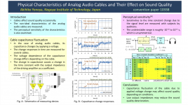
With regard to other cables, there are a couple papers and a poster.
https://www.aes.org/images/e-lib/thumbnails/2/0/20555_full.png
IIRC in another thread jneutron criticized the measurement technique in at least one of the presentations linked or attached. Again IIRC, his point was more or less along the lines that effects should be more dramatic in a transient case (presumably as opposed to sine wave-based and or some time-averaged measurements) since the path current takes through wire changes dynamically with time-rate of change of current (dynamically changing skin effect, proximity effect, and eddy currents), but proper measurement of those effects would be much more difficult than what the paper author did. IMHO perhaps a case where phase-free spectral analysis could be misleading 🙂
Attachments
Last edited:
After reading Cyril Bateman articles, I was curious to build a reflection bridge to test myself what he found. I had found this link which helped me understand how it works.
https://www.giangrandi.org/electronics/tandemmatch/tandemmatch.shtml
I have built three versions of the reflection bridge. Cyril Bateman experiment is reproducible.
Also the impedance testing is doable (Amp Zout, Cable Z, Load Z), providing the most meaningful information as Pavel has shown above.
All these due to long term (intellectual) agitation from JNeutron and Co
🙂
George
Attachments

Fascinating & way over my head. I would love to improve our cat5 wires.
- Home
- General Interest
- Everything Else
- Zip cord for speaker test