Tying the plates together will get you a Damping Factor of about 3, similar to the result in a common
low mu triode amp. Read 45, 2A3 & so on. But the audio power available will be only about 1.5 watts.
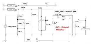
So here is an attempt to get a better DF by using some common voltage Negative Feedback.
I've taken the NFB from the secondary of the output transformer since that will to an extent compensate
for the OPT secondary winding resistance. This connexion also reduces the effect of power supply hum in
the output of the amplifier. Neither of these advantages occur in an amplifier using Schade NFB.
With the FB network in this simulation the NFB is ~6DB. The resulting DF is ~1.75.
The DF without NFB is ~0.33, similar to a common pentode. 3V in gets about 3 Watts out.
Clearly, the amp could use a little more gain, a higher mu tube in the front end would help a lot. 🙂
Do you have another tube in mind to put there?
low mu triode amp. Read 45, 2A3 & so on. But the audio power available will be only about 1.5 watts.
So here is an attempt to get a better DF by using some common voltage Negative Feedback.
I've taken the NFB from the secondary of the output transformer since that will to an extent compensate
for the OPT secondary winding resistance. This connexion also reduces the effect of power supply hum in
the output of the amplifier. Neither of these advantages occur in an amplifier using Schade NFB.
With the FB network in this simulation the NFB is ~6DB. The resulting DF is ~1.75.
The DF without NFB is ~0.33, similar to a common pentode. 3V in gets about 3 Watts out.
Clearly, the amp could use a little more gain, a higher mu tube in the front end would help a lot. 🙂
Do you have another tube in mind to put there?
Attachments
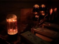
I don't know if there's any "general rule of thumb". Maybe the more technically inclined can provide one. Running it at 80% of its maximum current rating wouldn't bother me at all. I've never thought about it in % terms but, I suppose, if it was over 90% I might consider something else.After the previous post, I stopped working on this circuit and have simply been listening to it because I like it so much. The 6N6Gs at 272V plate-to-ground and the 27s at 140Vak/4.7mA just works really, really well.
Current question is about the power supply. There's a single 5Y3GT rectifying the whole amp. I measure the total current draw at exactly 100mA, which is 80% of the 5Y3GT's rated maximum output current of 125mA. Is that too high? What would be a general rule of thumb for what percentage of max current draw to use?
One thing to watch for, besides the current, is the value of the first cap in your PS. How large is it? The data sheet lists a maximum cap input filter value of 20uf.
It's important to note that the first cap value in the data sheets doesn't apply in all circumstances, though. In some data sheets there are 3 charts which serve as tests to see if a rectifier is safe to use under the conditions present in a specific amp. If it passes all 3 tests, the configuration is safe. I don't routinely use the process but it comes in handy. Generally, the specs listed are the maximums and if one or more are lower than the maximum you may be able to safely increase one of the other parameters, such as the cap value. That's where the 3 part test comes in.
https://tubedata.edebris.com/sheets/127/5/5Y3GA.pdf
I would only make two suggestions. First, use an old production American rectifier, not a modern production one from ?? - Russia? China? The other is that you might want to see if you can find a 6087 to use in place of the 5Y3GT. It's basically an indirectly heated version of the 5Y3GT (which is directly heated). A 6087 will give you a slow startup, which I prefer. They're not very common, however, and there's nothing wrong with a good 5Y3GT.
Glad to hear you're enjoying the amp. It sounds like it's very similar to the one I built, which I call the Nuance.
https://www.audiokarma.org/forums/index.php?threads/the-nuance-my-inverted-set-diy-project.990205/
It seems like the main difference is that I used a 26 input tube, which is very similar to the 27. The main difference being that the 27 is indirectly heated and the 26 is directly heated.
Please post some pics when you get a chance.
Current question is about the power supply. There's a single 5Y3GT rectifying the whole amp. I measure the total current draw at exactly 100mA, which is 80% of the 5Y3GT's rated maximum output current of 125mA. Is that too high? What would be a general rule of thumb for what percentage of max current draw to use?
----------------------------------------------------------------------
Best plug in replacement is a 5V4G/GA. Your present PS looks OK to me tho. 🙂 🙂
----------------------------------------------------------------------
Best plug in replacement is a 5V4G/GA. Your present PS looks OK to me tho. 🙂 🙂
Charlie is correct, the 5Y3 limit with cap input is 20 microF. My bad, I'm still on your
first page schematic with the 5U4G. A very different animal.
But the amp does need more gain so that the DF problem can be solved.
Otherwise the amp as is has very little control on the speaker, not a good thing.
A high mu triode on the front end would fix that with a minor circuit rearrangement.
first page schematic with the 5U4G. A very different animal.
But the amp does need more gain so that the DF problem can be solved.
Otherwise the amp as is has very little control on the speaker, not a good thing.
A high mu triode on the front end would fix that with a minor circuit rearrangement.
I don't know how to calculate the DF but I don't doubt that the changes you suggest would increase it.But the amp does need more gain so that the DF problem can be solved.
Otherwise the amp as is has very little control on the speaker, not a good thing.
A high mu triode on the front end would fix that with a minor circuit rearrangement.
I don't normally listen to a lot of thumpy, bass heavy music. But when I do play material like that, the bass is quite solid, not flabby at all to my ears. Now I'm not talking about the most extreme examples of this - not the stuff that the boom boom car stereo nuts play that rattles the body panels of their cars and shakes the surrounding neighborhood. But it's pretty deep and thumpy.
Looks like it would be easy enough for jdrouin to try increasing the DF while still using the 27 since he's using cathode bias. Your schematic is quite confusing to me, though. Not sure what all the stuff under the 6N6G label represents. And the OT seems to be push pull with one side grounded?
Since I'm using battery bias on the grid with the 26s I assume I'd need to use some type of plate to plate "Shade type" feedback. My amp is finished so I doubt I'll be modding it anytime soon, though.
I've never tried local, "Shade type", feedback but I'll probably need to on my next build which will likely be a SE using the directly heated 47 pentode for the outputs. I'm toying with the idea of trying a triode wired 47 for the input tube. If that doesn't work well I've got a few other DHPs I want to try.
It looks like the 47 is almost as easy to drive as the 6N6G. If I had thought of it when I was breadboarding the Nuance I could have tried the 47 in place of the 6N6G with the 26 front end or tried to drive the 6N6G with a 47. Oh well.
I also want to try a couple of DHP transmitting output tubes, the HY1269 and the 2E22. I'll be breadboarding all of these, of course. Probably over the summer.
I don't know how to calculate the DF but I don't doubt that the changes you suggest would increase it.
=================
DF can be read straight off the data sheet. To a very good first approximation it is simply
plate load divided by plate resistance. So taking the published specs fpr the 6N6G that would be 7000 / 24000............................................DF = 0.29, For a beam tube or pentode we can safely
ignore the OPT winding resistances.
But the approx is still close for a triode, when the OPT winding resistances are calc'd in the
DF drops a little. A well designed SET would have a DF of 3-4.
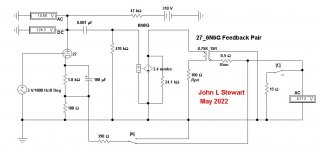
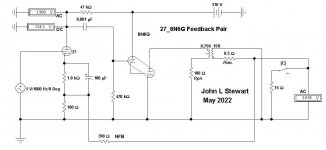
The schematic is something used by designers as a convenience to get quick but accurate results. Where the 6N6G is labelled we have a current generator of 2.4 mA per volt in.
In parallel with that is the plate resistance of 24K, all read straight off the data sheet.
So very quick to plug in the data for any tube & load to get quick results.
This is also used extensively in all the text books on the subject.
There is similar short cuts in the SS World. 🙂
I'll post something later that will be easier to read.
The bottom line tho is 'If it sounds OK to the user it is OK'.
=================
DF can be read straight off the data sheet. To a very good first approximation it is simply
plate load divided by plate resistance. So taking the published specs fpr the 6N6G that would be 7000 / 24000............................................DF = 0.29, For a beam tube or pentode we can safely
ignore the OPT winding resistances.
But the approx is still close for a triode, when the OPT winding resistances are calc'd in the
DF drops a little. A well designed SET would have a DF of 3-4.
The schematic is something used by designers as a convenience to get quick but accurate results. Where the 6N6G is labelled we have a current generator of 2.4 mA per volt in.
In parallel with that is the plate resistance of 24K, all read straight off the data sheet.
So very quick to plug in the data for any tube & load to get quick results.
This is also used extensively in all the text books on the subject.
There is similar short cuts in the SS World. 🙂
I'll post something later that will be easier to read.
The bottom line tho is 'If it sounds OK to the user it is OK'.
Do you have another tube in mind to put there?
I’m planning to try medium gain triodes 6J5, 6SN7, and 2C22 (amplification factor of ~20).
I also have 8532, 5842, and 6SL7.
There might even be 6SF5 and 6SQ7 knocking around.
I’ve also got standard input pentodes like 6J7, 6SJ7, 6C6, 310A.
Thanks for the input re: rectifier. 5V4GA resulted in higher than desired voltage when tried a few weeks ago. Right now I’m using the 300-0-300 HT windings with GZ34 and a 10H choke in front of the most recently posted PS rail. B+ is 266V with the 6N6G at 262V plate to ground and the 27 at about 130V across the tube. It sounds good; pretty similar to how it did running 5Y3GT into a capacitor and 6N6G at 272V with 27 at 140V.
DF can be read straight off the data sheet. To a very good first approximation it is simply
plate load divided by plate resistance. So taking the published specs fpr the 6N6G that would be 7000 / 24000............................................DF = 0.29, For a beam tube or pentode we can safely
ignore the OPT winding resistances.
But the approx is still close for a triode, when the OPT winding resistances are calc'd in the
DF drops a little. A well designed SET would have a DF of 3-4.
To get a damping factor of 3-4, then the plate and load resistances would almost need to be reversed: 24k/7k = 3.4.
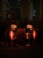
I’ve been listening to my very lovely 0.29 DF amp for a while this evening through unfiltered 15 ohm Lowther PM6A in self-made trapezoidal Onken cabinets 😆
https://instagram.com/p/CCZUHqEDx2f/
Searching around to learn about DF and don’t understand why a higher gain input tube would increase what seems to be a function of the plate/load impedance ratio.
If it wasn’t clear in the previous message, my PS is now a choke input, with 600Vct into GZ34 into a 10H Hammond 159P into the existing rail from the previous posts. B+ is now 266V. I’ve read choke input can “tighten the bass” as compared to a capacitor input but not sure if that’s just an urban legend.
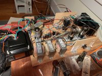
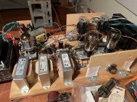
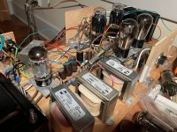
PS — Charlie, here some pictures, at your request.
Attachments
-
 02C67CF6-ABF7-45F7-AFEF-34CED998A74A.jpeg664.7 KB · Views: 100
 -
 8149F644-6510-4662-8FB1-D5FA76391A14.jpeg608.9 KB · Views: 83
 -
 53A4BB8A-5DE7-465B-B4E1-AE30D12C294D.jpeg323.4 KB · Views: 82
 -
 CF5C04F6-2C31-43CE-99F4-97F5D2AE407D.jpeg300 KB · Views: 89
 -
 59E1555F-C2DC-4284-972B-5B430CB1E751.jpeg596.8 KB · Views: 92
Last edited:
Looks like it would be easy enough for jdrouin to try increasing the DF while still using the 27 since he's using cathode bias. Your schematic is quite confusing to me, though. Not sure what all the stuff under the 6N6G label represents. And the OT seems to be push pull with one side grounded?
--------------------------------
Here is the schematic in the form common here on DIY. The OPT image is just that, it can be used in the diagram as SE or PP. It is customary to connect the secondary to common/ground to avoid a failure that put HV on the speaker leads. It is also the return lead for the NFB circuit.
The OPT secondaries of early receivers were not connected to anything but the speaker. But those systems were all closed with
no intended access for the user. Read 'kitchen AC/DC receiver'. They wouldn't pass UL now.
Since I'm using battery bias on the grid with the 26s I assume I'd need to use some type of plate to plate "Shade type" feedback. My amp is finished so I doubt I'll be modding it anytime soon, though.
------------------------------------
Schade NFB is vastly over rated here on DIY for the reasons I stated on the earlier post. I never use it & probably never will.
In 70+ years I've built about 50 different audio amps both SE & PP. With & without NFB. Pentode/Triode, pick any combo!!
And a lot of other gear.
I've never tried local, "Shade type", feedback but I'll probably need to on my next build which will likely be a SE using the directly heated 47 pentode for the outputs. I'm toying with the idea of trying a triode wired 47 for the input tube. If that doesn't work well I've got a few other DHPs I want to try.
--------------------------------------------
The 47 came & went in about a day. Tubes improved very quickly, soon as directly heated versions like the 2A5, 6F6, 6K6, Etc came
the DHT were out. With the exception of the 300B, in PP & PPP they make great theater amplifiers.
It looks like the 47 is almost as easy to drive as the 6N6G. If I had thought of it when I was breadboarding the Nuance I could have tried the 47 in place of the 6N6G with the 26 front end or tried to drive the 6N6G with a 47. Oh well.
------------------------------------------------------
The 47 won't get you as much audio as the 6N6G, look at the numbers on the data sheet. But an interesting comparison for those with time.
I also want to try a couple of DHP transmitting output tubes, the HY1269 and the 2E22. I'll be breadboarding all of these, of course. Probably over the summer.
-------------------------------------------------
That is an ambitious undertaking. The data sheets on those toobz are full of information on what to do for Class C RF & Class AB2
audio. Where do you intend to find the information on how to power up & bias in Class A SE? The HV can be deadly,
even for the experienced experts here on DIY. Many of these projects would never pass the kids, kats or fire test.
The switch 'C' in the schematic allows disconnecting the 15R load. The change in voltage is divided by the change in current to tell us
the internal impedance of the amp. That is compared to the 15R load, the result is the DF.
There is a lot of advice here on DIY, some good & a lot misleading & even dangerous. Be careful whose advice you follow.
I'll put something up for jdrouin tomorrow using one of his high mu triodes. With an explanation that makes sense.
Attachments
Last edited:
Thanks for the pics, Jeff . . . your breadboard looks better organized than mine usually does. And those speakers are gorgeous! Bet they sound good too.To get a damping factor of 3-4, then the plate and load resistances would almost need to be reversed: 24k/7k = 3.4.
I’ve been listening to my very lovely 0.29 DF amp for a while this evening through unfiltered 15 ohm Lowther PM6A in self-made trapezoidal Onken cabinets 😆
https://instagram.com/p/CCZUHqEDx2f/
Searching around to learn about DF and don’t understand why a higher gain input tube would increase what seems to be a function of the plate/load impedance ratio.
If it wasn’t clear in the previous message, my PS is now a choke input, with 600Vct into GZ34 into a 10H Hammond 159P into the existing rail from the previous posts. B+ is now 266V. I’ve read choke input can “tighten the bass” as compared to a capacitor input but not sure if that’s just an urban legend.
PS — Charlie, here some pictures, at your request.
I was told that using plate chokes instead of a resistor to load the input tube would increase the drive. The little Hammond 156C is inexpensive and can handle up to 8mA. Plate chokes that can handle more current seem to be much more expensive.
I'll be interested to hear your impressions of whatever different input tubes you decide to try. All the ones I tried were low mu DHTs and a triode strapped DHP. That was in keeping with my plan of using the "inverted SET" topology in which the input tube is directly heated and the output is indirectly heated and easy to drive.
John - I want to try Schade FB, partly out of curiosity, but also because I like to use battery grid bias on the input tube. Are there other FB methods, besides Schade plate to plate, that would work with that type of bias?Looks like it would be easy enough for jdrouin to try increasing the DF while still using the 27 since he's using cathode bias. Your schematic is quite confusing to me, though. Not sure what all the stuff under the 6N6G label represents. And the OT seems to be push pull with one side grounded?
--------------------------------
Here is the schematic in the form common here on DIY. The OPT image is just that, it can be used in the diagram as SE or PP. It is customary to connect the secondary to common/ground to avoid a failure that put HV on the speaker leads. It is also the return lead for the NFB circuit.
The OPT secondaries of early receivers were not connected to anything but the speaker. But those systems were all closed with
no intended access for the user. Read 'kitchen AC/DC receiver'. They wouldn't pass UL now.
Since I'm using battery bias on the grid with the 26s I assume I'd need to use some type of plate to plate "Shade type" feedback. My amp is finished so I doubt I'll be modding it anytime soon, though.
------------------------------------
Schade NFB is vastly over rated here on DIY for the reasons I stated on the earlier post. I never use it & probably never will.
In 70+ years I've built about 50 different audio amps both SE & PP. With & without NFB. Pentode/Triode, pick any combo!!
And a lot of other gear.
I've never tried local, "Shade type", feedback but I'll probably need to on my next build which will likely be a SE using the directly heated 47 pentode for the outputs. I'm toying with the idea of trying a triode wired 47 for the input tube. If that doesn't work well I've got a few other DHPs I want to try.
--------------------------------------------
The 47 came & went in about a day. Tubes improved very quickly, soon as directly heated versions like the 2A5, 6F6, 6K6, Etc came
the DHT were out. With the exception of the 300B, in PP & PPP they make great theater amplifiers.
It looks like the 47 is almost as easy to drive as the 6N6G. If I had thought of it when I was breadboarding the Nuance I could have tried the 47 in place of the 6N6G with the 26 front end or tried to drive the 6N6G with a 47. Oh well.
------------------------------------------------------
The 47 won't get you as much audio as the 6N6G, look at the numbers on the data sheet. But an interesting comparison for those with time.
I also want to try a couple of DHP transmitting output tubes, the HY1269 and the 2E22. I'll be breadboarding all of these, of course. Probably over the summer.
-------------------------------------------------
That is an ambitious undertaking. The data sheets on those toobz are full of information on what to do for Class C RF & Class AB2
audio. Where do you intend to find the information on how to power up & bias in Class A SE? The HV can be deadly,
even for the experienced experts here on DIY. Many of these projects would never pass the kids, kats or fire test.
The switch 'C' in the schematic allows disconnecting the 15R load. The change in voltage is divided by the change in current to tell us
the internal impedance of the amp. That is compared to the 15R load, the result is the DF.
There is a lot of advice here on DIY, some good & a lot misleading & even dangerous. Be careful whose advice you follow.
I'll put something up for jdrouin tomorrow using one of his high mu triodes. With an explanation that makes sense.
I did build a SE 6BQ5 amp that used cathode feedback since it didn't have an input / driver tube. The cathode FB allows it to be used with any separate preamp. Surprisingly, it even works without any preamp at all. It doesn't make full power like that but it's certainly useable.
https://www.audiokarma.org/forums/index.php?threads/voice-of-music-se-6bq5-w-local-nfb-build.926391/
I know the 47 is low power, about the same as the 45. I have a 45 SET I built years ago so I kinda know what to expect in terms of power output. I actually got interested in the 47 many years ago after reading about a PP 47 amp designed by Gary Pimm that got a lot of praise at the time. It also used Schade feedback, as I recall.
The HY69 / 1269 data sheet includes operating points for Class A in both SE and PP and also AB. In Class A the plate voltages range from 300v to 500v. I have no interest in the high voltage transmitter tubes.
https://tubedata.edebris.com/sheets/084/h/HY69.pdf
The data sheet for the 2E22 only lists Class C but I've seen a few schematics / operating points where people have used it in Class A, albeit triode strapped.
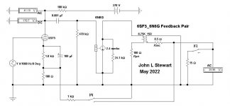
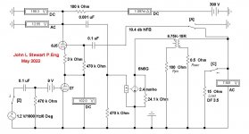
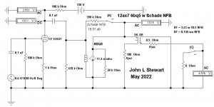
Here then is the 'Real Deal', subbing in a 6SF5 for the first stage of the amplifier.
Instead of a DF of 0.29, a few simple changes result in a DF of 3.66, about the same as a SET with a 2A3 or 45 as the power stage.
To see how the numbers are arrived at in simulation A the voltmeter at the output registers 25.96.
When the switch 'A' is transferred in Sim B to connect NFB the VM now sez 7.655. So NFB is 20 the log of 25.96 / 7.655 or 10.6 db.
That will reduce the distortion in the amplifier to 1/3 of what it would be without NFB.
To estimate DF we need to know the impedance of the amplifier looking back into the OPT.
Opening switch 'C' in Sim C disconnected the load resister & the voltage rises to 9.745.
The amp internal resistance is the change of voltage divided by the change of current.
The change of voltage is 9.745 - 7.655.........................................2.09
The change of current is 7.655 / 15 to zero..............................0.5103
So stuffing the numbers in the amp resistance is 4.096R
DF is 15 / 4.096 .......................................................3.66
Refer to my earlier schematic in this thread shewing how the circuit looks with the 6N6G rearranged.
Looking at the data sheet for a 2A3, by eyeball we can see DF is a little better than 3 for a bare bones circuit.
The OPT would drop that, so DF of 3 for an in circuit 2A3 is a good estimate.
The tube that the NFB is applied to changes gain, not the power tube.
I became home to a black wood tick (read Lyme Disease) a couple of weeks ago, it was on me a few days before I noticed.
Seems like there are more benefits to running chain saws & wood splitters than I'd previously thought.
So I did the first blood letting today for the required tests for Lyme Disease. Another set of tests in 2 wks.
No symptoms yet, but taking no chances either!
Attachments

There is another alternative, I'll get back to you on that later. 👍John - I want to try Schade FB, partly out of curiosity, but also because I like to use battery grid bias on the input tube. Are there other FB methods, besides Schade plate to plate, that would work with that type of bias?
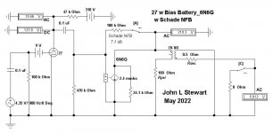
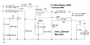
OK Charlie, here it is with the battery biased 27 as you had requested.
The DF is 3.5, same as a well designed triode amp like a SE 2A3 or 300B.
Any distortion caused by the 6N6G & the OPT is reduced by 2/3.
The extra gain required is got by Cascoding a 6J5 onto the 27 plate circuit.
The 6J5 can be anything similar like 6C4, 6C5, half 12AU7, half 6SN7, 2C22
& others. Whatever is in your stash. All triodes, should look & run well.
1.2 VRMS on the input drives to full output.
The 6N6G fits into the schematic again as I shewed a while back. 🙂
Attachments
Thanks, John . . . I guess I should have been more specific.OK Charlie, here it is with the battery biased 27 as you had requested.
The DF is 3.5, same as a well designed triode amp like a SE 2A3 or 300B.
Any distortion caused by the 6N6G & the OPT is reduced by 2/3.
The extra gain required is got by Cascoding a 6J5 onto the 27 plate circuit.
The 6J5 can be anything similar like 6C4, 6C5, half 12AU7, half 6SN7, 2C22
& others. Whatever is in your stash. All triodes, should look & run well.
1.2 VRMS on the input drives to full output.
The 6N6G fits into the schematic again as I shewed a while back. 🙂
I was wondering if there was a way to employ NFB without changing the basic topology of using a single input tube, that uses battery bias on the grid, to drive the output tube. In this case that's a 6N6G but, again, I'm considering output tubes like the 47, HY1269 and 2E22 for future builds.
I want to try using another 47 (in triode) to drive the 47 output. If that doesn't work well enough I've got a few other ("uncommon") tubes in mind, which I was considering using with the HY1269 or the 2E22, using the same topology - a single input tube that uses battery grid bias. Hence my question.
I'm guessing that such a topology would then restrict the possible NFB methods to some type of "Schade" type, plate to plate, arrangement or a cathode feedback scheme similar to the one I used in the SE 6BQ5 amp I linked earlier, which has no input tubes at all. The cathode feedback allows it to be used with any external preamp or (surprisingly) even as a "spud" with only a line level input.
So, other than those two possibilities, is there an additional type of NFB scheme I'm not aware of?
As always, your experience and expertise are greatly appreciated.
OK Charlie I hear you. But the 27/6N6G & others like it have a fundamental problem, not enough gain.
We used to design the power amp so that full output was possible with an audio input of about One Volt.
In the simulations we see the 27 gain to be ~7.5. It would not be much different for either 26 or 30.
Unless PFB is used, the gain can never be more than MU. Your Hammond choke loading will make
very little difference to the 27s gain.
The 6N6G doesn't have a lot oh gain either compared to a 6BQ5.
I'm thinking the 6BQ5 amp you saw was probably driven by something like a 12AX7, that was common.
Its easy to apply either Schade of full NFB in that kind of circuit.
In the simulations the gain of each stage can be read from the ratio of the output voltage to the input.
So for the 27_6N6G amp driven by one volt that would be 7.547.
And the 6N6G stage Gain is 116.6 / 7.547 or 15.64. As a cross check of the output stage,
use gain for a pentode is approx Gm Rl........So 2.4 X 7..........16.8..........Close enough, its an approximation.
But only 1.25 watts output. Schade FB will require a lot more drive.
So the 2nd simulation shews that. To get full output of 4.5 watts with 7 db FB the drive needs to be 4.35 volts.
Contrast that to a more recent amp where a 12AX7 drives a 6BQ5 in the other simulations.
So having enough gain does make a significant difference.
To make your 6N6G fly the circuit needs a driver like a 6SF5 or similar.
Or cascode the 27 as in the earlier sim.
The 12AX7/6BQ5 amp attains full output with a 0.6 volt input signal.
Attachments


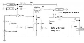
These simulations shew the Damping Factors of the two amps. The 27/6N6G combo barely makes it past DF of one
with NFB of ~7DB. Have to keep in mind that for every DB of NFB we use the driving voltage to the amp increases
by a similar amount. The drive required by this amp with NFB is already very high at the front end.
OTOH, the 12AX7/6BQ5 amp manages a DF of 3.23 with NFB of 18.5 DB.
And needs only 0.6VRMS for full output to the 8R load.
For these simulations I've corrected the OPT primary impedance to that recommended on the respective
data sheets for those tubes.
The substitution of a voltage controlled current source for a pentode that we see in a normal diagram was a
great time saver for us geezers with sliderules designing anything with tubes. There is a similar sub for triodes.
This allowed us to check the important parts of a proposed circuit by quickly changing only two numbers.
When this phase is completed than we would spend time on providing the DC conditions to operate the tubes.
As I'd pointed out in an earlier post, Schade NFB is highly over rated these daze. It doesn't correct for the
resistance of the OPT windings. It simply adjusts the voltage at the input to the OPT.
Then the OPT reflected secondary & primay resistance are in series between the load & output tube plate.
It also accentuates the ripple from the PS. I'll put something on here later to shew that.
Today's loudspeakers are for the most part designed for amplifiers with large DFs.
That being the case it seems to make sense to get a good DF.
So in an A/B listening test its a sure thing these amps will sound different.
Its up to the user to choose which way to go. Everyone has a preference.
I'm a very passive listener, much more interested in circuit is & outs! 😱
But the Rolling Stones, Pink Floyd & Bach still sound good.
Attachments
Yeah, I realize that NFB reduces the gain so a higher mu input tube is necessary. Part of the "formula" for the "inverted SET" (iSET) topology that I was employing in my Nuance is the use of a DHT input tube and most all of them are low mu (under 10), so I didn't really consider adding NFB to my original design.These simulations shew the Damping Factors of the two amps. The 27/6N6G combo barely makes it past DF of one
with NFB of ~7DB. Have to keep in mind that for every DB of NFB we use the driving voltage to the amp increases
by a similar amount. The drive required by this amp with NFB is already very high at the front end.
OTOH, the 12AX7/6BQ5 amp manages a DF of 3.23 with NFB of 18.5 DB.
And needs only 0.6VRMS for full output to the 8R load.
For these simulations I've corrected the OPT primary impedance to that recommended on the respective
data sheets for those tubes.
The substitution of a voltage controlled current source for a pentode that we see in a normal diagram was a
great time saver for us geezers with sliderules designing anything with tubes. There is a similar sub for triodes.
This allowed us to check the important parts of a proposed circuit by quickly changing only two numbers.
When this phase is completed than we would spend time on providing the DC conditions to operate the tubes.
As I'd pointed out in an earlier post, Schade NFB is highly over rated these daze. It doesn't correct for the
resistance of the OPT windings. It simply adjusts the voltage at the input to the OPT.
Then the OPT reflected secondary & primay resistance are in series between the load & output tube plate.
It also accentuates the ripple from the PS. I'll put something on here later to shew that.
Today's loudspeakers are for the most part designed for amplifiers with large DFs.
That being the case it seems to make sense to get a good DF.
So in an A/B listening test its a sure thing these amps will sound different.
Its up to the user to choose which way to go. Everyone has a preference.
I'm a very passive listener, much more interested in circuit is & outs! 😱
But the Rolling Stones, Pink Floyd & Bach still sound good.
The other part of the iSET equation is using an output tube that doesn't require much drive.
To my knowledge, there are several output tubes that are feasible. Those would include the 6BQ5, 7591, 6V6, 6N6G and 47 (and their relatives). There are probably others I'm not aware of, too.
And I wasn't too concerned about the traditional design criteria that the output tube should be driven to full power with a 1v input signal. Partly, it's because modern sources, like a CD player or DAC, have 2v outputs, although their average output is likely closer to 1v.
The other factor is that I just don't see how it would make that much difference in terms of sound output, given that it takes 2x the power to produce a 3db increase in volume. So the difference between driving the output tube to only 50% power vs full power is only 3db. If you're driving the output tube to 75%, the difference between that and full power will be only ~1db, which is basically unnoticeable to the ear.
For me, this all works fine because I don't listen at high volumes anyway. If I did, I probably wouldn't be building low wattage amps. If I need more drive, I can always add a preamp. And if the bass doesn't sound as solid as I'd like, I have the option of using an active crossover and a higher power Class D amp for the bass. This also reduces the demands put on the tube amp.
I'm still perplexed by your diagrams but perhaps it's due to my ignorance of Schade feedback schemes. I always thought that Schade used a resistor between the plate of the output tube and the plate of the input tube - with the connection made to the input side of the coupling cap. In your diagram it seems like the resistor is between the plate of the output tube and the grid of the output tube, since it's connected on the output side of the coupling cap, which connects to the output tube's grid.
On my Nuance build, I took your advice and connected the plates of the 6N6G sections together. This seems to mimic the effects of having NFB - it tightens up the bass and output is lower - so I assumed it was creating some NFB. I suspected it might be technically different from Schade simply because the input section of the 6N6G is configured as a cathode follower. Otherwise it seems like it would amount to 100% feedback between the two plates, since there is no resistor. But, again, I've never spent any time studying Schade FB so maybe I'm way off here.
I bought two pairs of the Rockola 6B5 PP amps about 20 years ago. Like 90% of what I buy, I’ve never done anything with them.
Has anyone played with them? I figure I have about 13 years left on terra firma (I just turned 67….. it sucks!), so I’m trying to reduce the 2500 square feet packed to the 10-12 foot ceilings of tube audio stuff I have acquired beginning at age 7.
Anyone think it’s worthwhile rebuilding a pair to try?
Peace,
Rick
On my 85th I biked on the kind that you gotta pedal 60 km in 3 hrs flat.I bought two pairs of the Rockola 6B5 PP amps about 20 years ago. Like 90% of what I buy, I’ve never done anything with them.
Has anyone played with them? I figure I have about 13 years left on terra firma (I just turned 67….. it sucks!), so I’m trying to reduce the 2500 square feet packed to the 10-12 foot ceilings of tube audio stuff I have acquired beginning at age 7.
Anyone think it’s worthwhile rebuilding a pair to try?
Peace,
Rick
But time duz march on, I gave away about 2/3 of my toob stash just before COVID.
These daze its chain saws & splitters. And a lotta other manual labor, the traffic here
got too dangerous for the bike. The hard hat doesn't protect for a fender too close.
But still dabbling in the odd project. And fanning the flames of controversial tube ccts.
- Home
- Amplifiers
- Tubes / Valves
- Developing a 6N6G Integrated Amplifier