Nothing wrong with the 45, of course, but it's a more expensive tube, especially NOS, and not as easy to find. I've never paid more than ~$25 for a NOS 6N6G and have, on occasion, found them for under $10.Deciding whether to buy more off ebay. If this is going to be a finicky tube then I’ll just develop a 45 amp.
I have a 45 SET amp, a very popular design that was developed by Gordon Rankin called the Bugle. It sounds really nice but the Nuance iSET sounds better. Much better, actually.
I'm not sure why, it may have nothing to do with the comparative merits of the 45 and the 6N6G. YMMV, as always, of course.
I already have a tranche of tested 45s, so the expense is not much of a concern. I'd need to purchase filament transformers and eventually PS chokes, but otherwise can use parts that are already lying around.
I've got a pair of Soviet 6C6C (or 6S8S in roman letters), which is a military-grade 2C22, that I wanted to try on input, with a 27 or 26 driver stage into the 45. Maybe a choke-loaded, DC-heated 26 DHT into the 45 would have the excellent qualities you've discovered in your 6N6G Nuance?
Anyway, I was curious to breadboard the Bugle circuit, too. We'll see. I've put in a question about a pair of 6N6Gs on eBay.
I have a PP 6B4G amp that uses 2C22s as input / phase inverters. Sounds really nice.I already have a tranche of tested 45s, so the expense is not much of a concern. I'd need to purchase filament transformers and eventually PS chokes, but otherwise can use parts that are already lying around.
I've got a pair of Soviet 6C6C (or 6S8S in roman letters), which is a military-grade 2C22, that I wanted to try on input, with a 27 or 26 driver stage into the 45. Maybe a choke-loaded, DC-heated 26 DHT into the 45 would have the excellent qualities you've discovered in your 6N6G Nuance?
Anyway, I was curious to breadboard the Bugle circuit, too. We'll see. I've put in a question about a pair of 6N6Gs on eBay.
I suspect that the sound quality I've achieved with the Nuance has more to do with the use of a DHT as an input tube than it does with using the 6N6G as the output. I can't say for sure, though.
I'm sure the 6N6G does bring something to the table. The PP amp I built with them has a pretty common front end and I think it sounds much better than it did with 6V6s. So it's certainly, not all about the front end.
During the breadboard phase I tried numerous DHTs and triode strapped DHPs but I always used the 6N6G for the output tube. I like playing with oddball tubes that are relatively cheap and, to me, it's such an interesting and unique design.
According to the data sheets, it also has a good combination of power and distortion. The power output figures quoted are at 5% distortion. Most data sheets for other output tube candidates seem to quote power output at 10% distortion and yet many of them produce less power. So, I assume they would produce even less at 5% distortion.
This was not a deciding factor for me, though. I'm not that technically oriented and have no way to measure such things. I just think it's a cool tube and I've enjoyed the sonic results when I've used it.
The iSET concept used in the Nuance is about using a DHT as an input tube with an easy to drive output tube. If I was going to use a less easily driven tube, like the 45, for the output, I'd try a 26 or similar DHT as input and then the 2C22 (or ??) as a driver.
I assume that could be done but, again, I'm not very technically savvy.
Note:
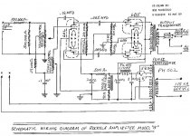
The .PDF 6N6G Data Sheet / Sales Document of Post # 19 shows a resistor from the input triode cathode to the output triode grid.
It does NOT show any resistor from the output tube cathode to the outside world.
No self bias, and only positive forward bias on the output tube . . . Ouch!
If you insist on using a 6N6G, you might try using an external resistor from the output tube cathode to ground.
Your Mileage May Vary (some others get less mileage than others, especially when there is no external cathode resistor, and no negative grid bias for the output tube.
But with an external cathode resistor, that degenerates the cathode of the input tube too.
So much trouble when you try to tube amplifier that uses a tube that is some companiy's engineer's/marketeer's bright idea to increase their sales of tubes.
Just my opinion (and may very well explain other's troubles with this tube).
Much of the data sheet is over my head so I can't comment on the engineering details. Perhaps my understanding of how the two sections are configured is incorrect. Frankly, I don't care how they're constructed as long as they work and sound good.Note:
The .PDF 6N6G Data Sheet / Sales Document of Post # 19 shows a resistor from the input triode cathode to the output triode grid.
It does NOT show any resistor from the output tube cathode to the outside world.
No self bias, and only positive forward bias on the output tube . . . Ouch!
If you insist on using a 6N6G, you might try using an external resistor from the output tube cathode to ground.
Your Mileage May Vary (some others get less mileage than others, especially when there is no external cathode resistor, and no negative grid bias for the output tube.
But with an external cathode resistor, that degenerates the cathode of the input tube too.
So much trouble when you try to tube amplifier that uses a tube that is some companiy's engineer's/marketeer's bright idea to increase their sales of tubes.
Just my opinion (and may very well explain other's troubles with this tube).
Not sure who is having trouble with the 6N6G, other than jdrouin's apparent issue with one bad tube.
No problems here and, as I've said, I've run at least a dozen of them in 3 different amps. A few commercial amps also used them back in the day, including a jukebox manufacturer, Rock-O-La, I think.
Rockolab pp 6B5. Same pinout as a power pentode.
Just remove the cathode resistor & cap & replace with a copper wire. Oxygen starved or not, your choice.
The 6B5 & similar tubes are self biasing. And a no brainer to simulate on the bench!
All Triode UL anyone??
Just remove the cathode resistor & cap & replace with a copper wire. Oxygen starved or not, your choice.
The 6B5 & similar tubes are self biasing. And a no brainer to simulate on the bench!
All Triode UL anyone??
Attachments
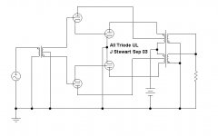
Positive grid is nontraditional but NOT illegal.does NOT show any resistor from the output tube cathode
This seems to be the only "novel" product from this tube maker. It is better than a simple neg-grid triode (more current for the size). It is perhaps not quite as good as a power pentode. Especially when those got into multiple suppliers. (I think the 6B6 and kin only came from TRIAD.)
Only that they distributed them. Or did once, or could if bribed.does that mean they made them?
Yeah, if it took-off like 6V6 (not an RCA invention), RCA would make them (eventually half the garages in the nation were banging out 6V6).
Far as I know the beam power tube is an English invention, refer to 'critical distance tetrode'.
The English couldn't afford to develope the concept so an exchange of patents occured between the US & UK.
The 6L6 & 6V6 appeared, 1937?? All in Wikipedia & sometimes found in olde textbooks.
The English couldn't afford to develope the concept so an exchange of patents occured between the US & UK.
The 6L6 & 6V6 appeared, 1937?? All in Wikipedia & sometimes found in olde textbooks.
Thanks for all that background info, jhstewart9 and PRR.
My "new" Tung-Sol 6N6Gs arrived today. Before I put them on the breadboard, I'll check all the connections again just to make sure everything's hunky-dory.
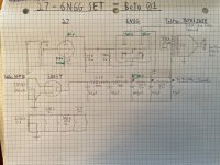
Figured I'd do a better draw-up of the current circuit (attached) to pass before the gallery before I put the new tubes in. If anyone spots any problems with this design, I'd appreciate it.
The green voltage and current numbers indicate targets, not measurements. I'll take those once I'm sure this circuit is safe for the new tubes.
My "new" Tung-Sol 6N6Gs arrived today. Before I put them on the breadboard, I'll check all the connections again just to make sure everything's hunky-dory.
Figured I'd do a better draw-up of the current circuit (attached) to pass before the gallery before I put the new tubes in. If anyone spots any problems with this design, I'd appreciate it.
The green voltage and current numbers indicate targets, not measurements. I'll take those once I'm sure this circuit is safe for the new tubes.
Attachments
Your Schema looks OK as is.
If the heater winding on the PT has a CT you could connect the 27 heaters in series across
the 6.3V with appropriate dropping resisters to 2.5V. That would be 0.4R in each leg.
If the heater winding on the PT has a CT you could connect the 27 heaters in series across
the 6.3V with appropriate dropping resisters to 2.5V. That would be 0.4R in each leg.
Basic circuit design looks OK.Thanks for all that background info, jhstewart9 and PRR.
My "new" Tung-Sol 6N6Gs arrived today. Before I put them on the breadboard, I'll check all the connections again just to make sure everything's hunky-dory.
Figured I'd do a better draw-up of the current circuit (attached) to pass before the gallery before I put the new tubes in. If anyone spots any problems with this design, I'd appreciate it.
The green voltage and current numbers indicate targets, not measurements. I'll take those once I'm sure this circuit is safe for the new tubes.
Another, somewhat simpler, option for getting power to the plate of the input section of the 6N6G is to just connect it directly to the plate of the output section.
I did this with mine on the advice of jhstewart9. I'm sure he can explain what this does from a technical standpoint. To me, the audible effect is similar to when I've added a touch of NFB in other amps I've built.
It tightens up the bass although it also produces a bit less power. I'm not real familiar with Lowther speakers but, as I recall, they are quite efficient so the lower power output shouldn't matter.
On my amp I made it switchable so I have the option of having a bit more power if I feel the need. So far, even with speakers that are only moderately efficient, I haven't felt like I really needed more power, though.
Thanks for the suggestions. I'll be trying a bunch of different things with this circuit over the next few weeks and will give all this a go.
Tonight I'm listening to the amp with the new Tung-Sol 6N6Gs and like it a lot. It's been running for about 90 minutes, no problem. I ended up using a 5Y3GT rectifier to bring the voltages down below maximum. Now B+ has settled in at a steady 288V, with about 282V on the output pin and 278V on the input pin. It needs something more like a 330R dropping resistor for the input pin to bring those closer to equal, so I'll pick one up after work tomorrow.
27s are running at 140Vak/4.7mA.
The 6N6Gs definitely sound happier at this voltage than they do at ~310V -- much less strident, more effortless.
The 5Y3GT is putting out about 89mA (of 125mA maximum).
Last edited:
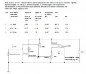
So you are building an amp with a couple of 27s in it. But like most PTs there is no 2.5V winding on your PT. Unless the 6.3V heater winding has a center tap (CT) you will have to use large dropping resistors to get the proper 2.5VAC you need for the 27s. But there is a slick way out that saves some current on the heater winding & creates less heat. If stereo is on your mind the heater supply could be a problem.
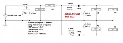
The simple circuit uses two diodes & two resisters in a symmetrical hookup so that there will be no DC on the PT heater winding. The limiting resisters are set at 0.75R, one in each leg. And the 27’s heater voltage is calculated using Root of Sum of Squares since both AC & DC are applied to the 27 heaters. The simulation assumes 2R for the PT primary & 0.05R for the 6.3V secondary, educated guesses. And the circuit uses One Amp per channel less than what we normal!y might do! And quite a bit less heat under the chassis.
Something to think about.
Attachments

Yes, see the schematic. There are 0.56R dropping resistors downstream of the 6N6Gs. Right now there is 2.6V on the 27 heaters, which I figure is close enough. Your method is certainly pragmatic, though, so maybe I'll try that at some point. Thank you for that.
I was trying to use all AC heat for the moment. At some point I'll be swapping in type 30 and then 26 DHTs as the input tubes, which will use DC on the filaments.
I just switched the 350R dropping resistor to the 6N6G input plate pin to 330R. It dropped the B+ to 282V, with 278V on the output plate and 274V on the input plate. I had thought that would bring their voltages closer to equal, but they are still 4V apart (it was 282/278V in post #34).
The increased current means that the 5Y3GT is now putting out 97.4mA of current (getting close to that 125mA max) and is definitely giving off some heat. I might need to switch to something like 5V4GA and use more dropping resistance in the PS. Or even raise the resistance to the input pins to lower the current and raise the overall voltage.
There's about 27mA flowing through the dropping resistor to the input pins. So, divided by 2, since it feeds both tubes, that means there's about 13mA on the input plate. 6N6G datasheet says there's supposed to be about 8 or 9mA there. Maybe getting the current through the dropping resistor is not the way to measure that. Or maybe there should be separate plate load resistors for each tube.
Man, sometimes I feel so dumb. That's 27mA through the 33R dropping resistor because all the 6N6G input and 27 plate currents are going through it. The math shakes out. And that's also probably why it's difficult to equalize the 6N6G input and output plate voltages.
I mean, it sounds good. But I should probably split all those out into separate plate load resistors. I'm pretty much out of room on the breadboard, though, and might have to make a new one for all these connections.
Funny thing is the 6N6G is supposed to reduce parts count, but with a 3-stage amp you're still making more connections than in a 2-stage amp, and that takes space.
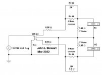
For the heater supply I see your 6.3V winding has a CT. Here is a simple way to save the 1.75 Amp of one of the 27s.
Might not be important for this build but something that may help in future.
When I write these responses I'm thinking as well regards all the lurkers out there trying to pickup some useful information.
I found long ago while authoring articles for Glass Audio, Etc that it makes sense to consider the wider audience,
their experience covers a wide range. So some of my responses may seem a little odd!
The 6N6G & similar tubes were never meant to replace two tubes, altho on the surface it may appear that way.
They are simply another idea that came out of the 1930s as rapid progress was being made.
There were several 'zero bias triodes' that could be driven to pentode like power in Class A2.
It was a simple step to go from driving with an interstage transformer to a cathode follower driven stage.
So several glass bottles like the 6N6G appeared, the market of the day had a new toy to play with!
Look at the plate curves of the 46 & 49, just like a pentode. Those plate curves result in poor damping
of the load. But connecting the driver plate to the output plate causes the same transformation as
happens when we triode connect a pentode. Less power but much better loudspeaker damping.
Try that with a switch as Charlie has, hear the difference!
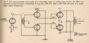
The PP 807 modulator is yet another example of this hookup.
Might not be important for this build but something that may help in future.
When I write these responses I'm thinking as well regards all the lurkers out there trying to pickup some useful information.
I found long ago while authoring articles for Glass Audio, Etc that it makes sense to consider the wider audience,
their experience covers a wide range. So some of my responses may seem a little odd!
The 6N6G & similar tubes were never meant to replace two tubes, altho on the surface it may appear that way.
They are simply another idea that came out of the 1930s as rapid progress was being made.
There were several 'zero bias triodes' that could be driven to pentode like power in Class A2.
It was a simple step to go from driving with an interstage transformer to a cathode follower driven stage.
So several glass bottles like the 6N6G appeared, the market of the day had a new toy to play with!
Look at the plate curves of the 46 & 49, just like a pentode. Those plate curves result in poor damping
of the load. But connecting the driver plate to the output plate causes the same transformation as
happens when we triode connect a pentode. Less power but much better loudspeaker damping.
Try that with a switch as Charlie has, hear the difference!
The PP 807 modulator is yet another example of this hookup.
Attachments
I'm getting ready to swap in a different input tube but will try tying together the two 6N6G plates first.
The other night I decided to get the operating points closer to 300V, so I swapped in a 5V4GA rectifier and added 195R of resistance before the reservoir cap. That ended up with a B+ of about 302V, with about 295V on the output plate and 292V on the input plate. The 27s were at 150Vak/5.5mA. I then listened for about 90 minutes on speakers, followed later by about an hour on headphones.
While it sounded a little more driven than at the lower op points (~ 278V & 274V on the 6N6G plate pins, about 140Vak/4.7mA across the 27s), it regained some of that stridency I was hearing earlier on. I found it mildly fatiguing to listen to. It's hard to say whether the 27s or the 6N6G, or both, are contributing to that stridency.
So last night I removed the 195R of resistance and put the 5Y3GT back in for comparison, and definitely prefer the 278V op point on the 6N6G and 140Vak/4.7mA on the 27s. I drew the load line for the 27 at 140Vak/4.7mA and it looks pretty linear (sorry, it's on my home computer and I'm currently at work, else I'd post it).
Anyway, I'm going to try tying the 6N6G plate pins together tonight. Then I'll try choke-loading the 27 plates to hear that difference, maybe over the weekend. Then next week some time I'll try a type 30 input tube with DC heating.
After the previous post, I stopped working on this circuit and have simply been listening to it because I like it so much. The 6N6Gs at 272V plate-to-ground and the 27s at 140Vak/4.7mA just works really, really well.
Current question is about the power supply. There's a single 5Y3GT rectifying the whole amp. I measure the total current draw at exactly 100mA, which is 80% of the 5Y3GT's rated maximum output current of 125mA. Is that too high? What would be a general rule of thumb for what percentage of max current draw to use?
Current question is about the power supply. There's a single 5Y3GT rectifying the whole amp. I measure the total current draw at exactly 100mA, which is 80% of the 5Y3GT's rated maximum output current of 125mA. Is that too high? What would be a general rule of thumb for what percentage of max current draw to use?
- Home
- Amplifiers
- Tubes / Valves
- Developing a 6N6G Integrated Amplifier