A while back I got interested in the 6N6G tubes because they contain a direct-coupled driver and output stage within the bottle. The ~4 watts output is perfect for my efficient full range driver speakers. They don't need much gain on the input, so I decided to start with a type 27 indirectly heated triode before moving on to direct-heated type 30 and 26 triodes. FlaCharlie has been working with this tube as well, so some of my experiments will likely be close to his.
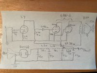
Here is a schematic of the first trial circuit that I've breadboarded. The 27s and 6N6Gs are AC-heated, all in parallel, using 0.56R/25W dropping resistors downstream of the 6N6Gs to get 2.5V for the 27s.
The 27s are currently running at about 172Vp, 11.5Vk, or ~160Vpk @ 5.75mA.
Rectifier is actually a 5R4GY.
The B+ is about 323V. For the 6N6Gs, after the OPTs there's about 315V on the output triode plate and about 305V on the input plate. There's supposed to be 300V on both triode plates, at least as I understand the datasheet, so I'll need to tweak that a bit. Unless that's supposed to be 300Vak as for a normal tube, but there's no way to get the cathode voltage because the resistor is inside the bottle. Either way, it is within the maximum operating point of the tube.
The OPTs are a bit odd: Tektron 3.5K with 6R and 10R secondaries. With my 15 ohm Lowthers on the 6R winding, that makes a reflected load impedance of 8.75K to the output triode plate. I've also connected the 10R secondary to a headphone jack, which with my 32 ohm cans will reflect a 11.2K load impedance to the output triode plate; I haven't listened to the headphones yet.
On speakers (Lowther PM6A in trapezoidal Onken, no filter), this version sounds like a typical SET amplifier; lots of detail and a lovely midrange, though on some recordings it can sound a bit strident. I did not put a cathode bypass cap on the 27 because I didn't need the gain. With the 100K volume pot turned up all the way and using Pandora on an old iPhone as source, it gets to the cusp of what I would consider uncomfortably loud. But the whole range of the pot is useful, which is nice.
I will also be experimenting with bypass caps for more gain and maybe even something like 6J5 or 6SN7 on input (maybe even as low gain cathode follower).
Attachments

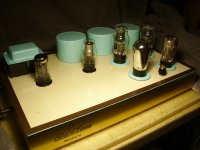
Yeah, I had mine breadboarded for most of last year and finally got it built. Here's a pic. As I usually do, I'm using a lot of repurposed materials and junkbox parts.A while back I got interested in the 6N6G tubes because they contain a direct-coupled driver and output stage within the bottle. The ~4 watts output is perfect for my efficient full range driver speakers. They don't need much gain on the input, so I decided to start with a type 27 indirectly heated triode before moving on to direct-heated type 30 and 26 triodes. FlaCharlie has been working with this tube as well, so some of my experiments will likely be close to his.
. . . There's supposed to be 300V on both triode plates, at least as I understand the datasheet, so I'll need to tweak that a bit. Unless that's supposed to be 300Vak as for a normal tube, but there's no way to get the cathode voltage because the resistor is inside the bottle. Either way, it is within the maximum operating point of the tube.
. . . I will also be experimenting with bypass caps for more gain and maybe even something like 6J5 or 6SN7 on input (maybe even as low gain cathode follower).
The plate voltages in the data sheet are plate to ground, since the cathode pin is grounded. The data sheet lists specs for 300v and 325v, which is the maximum.
The input section of the 6N6G is already a cathode follower that's directly connected internally to the output section. If you decide you want a bit more gain than the 27 provides you might try the 56, which has a mu of 13.8, as I recall. Both of those are available as globes as well as STs.
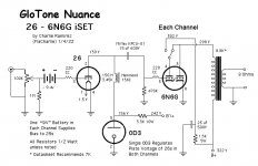
I'm using choke loaded 26s up front. The 27 is essentially an indirectly heated version, or close enough, so it should be simpler to implement. I wanted to try the "inverted SET" concept (iSET) so all the input tubes I experimented with were DHTs. I tried a bunch of them but kept coming back to the 26.
First time I've built anything with directly heated input tubes. I was initially concerned that I might have hum issues but with DC heating on the input tubes it wasn't an issue. One thing that surprised me was the difference between the ST and globe versions of the 26. Both are wonderful and I like the fact that switching between them allows the presentation to be tailored to the music.
Here's a build thread with details, more pics and schematics:
https://www.audiokarma.org/forums/index.php?threads/the-nuance-my-inverted-set-diy-project.990205/
Attachments
I put them in an SSE board. Fun tube to play with. There's a short thread with a few pictures and maybe some measurements in the Tubelab sub forum.
Win W5JAG
Win W5JAG
Inverted How???
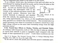
The Inverted Triode Circuit was originally described in 1928(?) by Terman & others where the plate of a triode is used as the input.
A useful concept for measuring high voltages. Steve Bench built experimental amplifiers using this kind of hookup.
The Inverted Triode Steve Bench
http://diyaudioprojects.com/mirror/members.aol.com/sbench102/inverted.html
And my look at it with some circuit ideas & measurement results in the pdf (6 pages).
Attachments
Not in a technical sense.Inverted How???
I think the term was coined by Andy Evans. It refers to the fact that, typically, SETs use directly heated output tubes which have higher drive requirements. None of the DHT input tubes can provide enough drive on their own for a 45, 2A3 or 300B, for example.
So, the concept here is to use an indirectly heated output tube that can be driven by a single low mu DHT input tube, like the 26, 01A, 10, 30, etc. It's a simpler and cheaper way to build an SET that incorporates a directly heated tube and allows you to use two tubes per channel.
Any output tube with low drive requirements can be used. Other candidates that come to mind are the 6BQ5, 7591, 6V6 and their relatives. Perhaps there are others.
BTW, in my build I incorporated your suggestion to connect the plates of the input and output sections of the 6N6G. I built it so it's switchable, which provides a bit more power when inefficient speakers are used.
Thanks for uploading those articles, I'll have to take a look.
I listened to this circuit on headphones last night -- 32 ohm DT-880, meaning a reflected load impedance of 11.2K. It sounded pretty good until after about an hour when the sound in the right channel cut out. I immediately pulled out my multimeter and found that the B+ had gone from about 320V down to about 174V. I quickly checked the 6N6G plates and their voltages were low too, plus something smelled really hot. So I turned off the amp and went to sleep.
Today I used the tube tester to assess all the tubes. The 6N6G in the right channel tested poorly, so I replaced it with a new one that tested strong. I measured while listening; it sounded fine but after a couple minutes of operation the same thing happened again. I tested all my 6N6Gs and 27s on hand, and tried swapping in different ones but the same thing keeps happening.
I then tested and tightened every connection on the breadboard, made sure nothing erroneous was making contact, etc., and it still happens.
The capacitance of the coupling caps measures fine. The 27 plate load resistors and the 1.2K dropping resistor in the PS rail measure accurate resistances. I wonder if one of these components went open, or if perhaps something on one of the tube sockets is amiss.
If anyone has thoughts on why this is happening, I'd really appreciate it. If I run it, it holds a steady operating voltage and plays music well for 2-3 minutes, but then starts losing voltage quickly.
Thanks,
Jeff
Hopefully you'll get some advice from some people who are better at troubleshooting than I am but here's what I noticed . . . If the schematic you posted in correct, you've got the power supply wired incorrectly.I listened to this circuit on headphones last night -- 32 ohm DT-880, meaning a reflected load impedance of 11.2K. It sounded pretty good until after about an hour when the sound in the right channel cut out. I immediately pulled out my multimeter and found that the B+ had gone from about 320V down to about 174V. I quickly checked the 6N6G plates and their voltages were low too, plus something smelled really hot. So I turned off the amp and went to sleep.
Today I used the tube tester to assess all the tubes. The 6N6G in the right channel tested poorly, so I replaced it with a new one that tested strong. I measured while listening; it sounded fine but after a couple minutes of operation the same thing happened again. I tested all my 6N6Gs and 27s on hand, and tried swapping in different ones but the same thing keeps happening.
I then tested and tightened every connection on the breadboard, made sure nothing erroneous was making contact, etc., and it still happens.
The capacitance of the coupling caps measures fine. The 27 plate load resistors and the 1.2K dropping resistor in the PS rail measure accurate resistances. I wonder if one of these components went open, or if perhaps something on one of the tube sockets is amiss.
If anyone has thoughts on why this is happening, I'd really appreciate it. If I run it, it holds a steady operating voltage and plays music well for 2-3 minutes, but then starts losing voltage quickly.
Thanks,
Jeff
The voltage coming off the second 47uf cap, after the 2nd choke, should supply B+ to the 6N6Gs in both channels. The input plates of the 6N6Gs connect directly to that cap and the output transformers also connect there. The third 47uf cap should supply only the two 27s.
The way you have it drawn, it looks like the third 47uf cap supplies voltage to the output section only of one 6N6G and and it's decoupled by a 1.2k 1w resistor. So it seems like you're running the both input sections of the two 6N6Gs, the output section of the second 6N6G and both 27s off the third 47uf cap.
At 300v the 6N6G is drawing a total of ~53mA and at 325 it's ~60mA so with your voltages, let's say that each 6N6G is drawing 55mA. Using Ohm's Law (if both sections of only one of your 6N6Gs is supplied by the cap after the 1.2k resistor) that resistor is dissipating 3.63w and it's only a 1w resistor.
Perhaps it's just a drawing error and B+ to both OTs is being supplied by the second 47uf cap. But even if you're running only the 27s and the input section of the two 6N6Gs off the last cap it's too much for that resistor. The 6N6G data sheet says each input section is drawing ~8mA and if you're also running each 27 at ~8mA, that's a total of 32mA. That would mean your 1w resistor is dissipating 1.23w.
The 1w rating is fine if that cap is only supplying the 27s, which is how it should be wired. But if you're pulling over 55mA through it, or even 32mA, it's gonna burn up.
Even if you're running the 27s at, say 10mA total, that would require that resistor to dissipate ~.8w. A resistor that dissipates .8w should, at a bare minimum, be rated at 3w. A good rule of thumb is that a resistor should be derated by a factor of 3x, although I prefer to go with 5x when possible.
What you smelled is likely that resistor overheating.
Last edited:
Of course, if you run the input section directly from the B+ the voltage will be a bit higher than the plate of the output section because of the loss in the OT. Some OTs will drop more than others.
Here's how I did it. As you can see, there's a switch that allows the plate of the input section to either be connected directly to the plate of the output section or to be supplied by its own cap.
I added that additional RC section in order to keep the voltages closer but I'm not convinced that it was really necessary. Traditionally, circuits that used this tube ran the input section directly from the B+. I tried it both ways and didn't hear any difference.
But the supply to the 27s should be decoupled from it and they should be run off a separate cap.
Attachments
Thanks, Charlie. My drawing shows the two halves of one 6N6G as separate tubes. That was my mistake.
What I did, and what my drawing ostensibly shows, was to try and have 300V on the pin of each 6N6G plate.
So, the 3rd 47uF cap (it's actually 100uF on the breadboard, btw) does the following:
The 1.2K resistor (to the 4th 47uF cap) is meant to drop the B+ to 300V on both 6N6G input plate pins.
If I had fed both 6N6G plate pins directly from the B+ rail, one would have a higher voltage than the other, and I was trying to get them both exactly to 300V.
Maybe that wasn't the right approach.
What I did, and what my drawing ostensibly shows, was to try and have 300V on the pin of each 6N6G plate.
So, the 3rd 47uF cap (it's actually 100uF on the breadboard, btw) does the following:
- Feeds the output section of both 6N6Gs via the OPT primaries.
- Feeds both 27s via the 27K plate load resistors
The 1.2K resistor (to the 4th 47uF cap) is meant to drop the B+ to 300V on both 6N6G input plate pins.
If I had fed both 6N6G plate pins directly from the B+ rail, one would have a higher voltage than the other, and I was trying to get them both exactly to 300V.
Maybe that wasn't the right approach.
The way you drew the different sections of the 6N6G didn't confuse me.Thanks, Charlie. My drawing shows the two halves of one 6N6G as separate tubes. That was my mistake.
What I did, and what my drawing ostensibly shows, was to try and have 300V on the pin of each 6N6G plate.
So, the 3rd 47uF cap (it's actually 100uF on the breadboard, btw) does the following:
- Feeds the output section of both 6N6Gs via the OPT primaries.
- Feeds both 27s via the 27K plate load resistors
The 1.2K resistor (to the 4th 47uF cap) is meant to drop the B+ to 300V on both 6N6G input plate pins.
If I had fed both 6N6G plate pins directly from the B+ rail, one would have a higher voltage than the other, and I was trying to get them both exactly to 300V.
Maybe that wasn't the right approach.
If you look at my schematic you can see that I also added a dropping resistor and another cap in order to run the input section at roughly the same voltage as the output section. That's the 1.5k 5w resistor and 25uf cap on my schematic. Works fine although, as I said, I didn't hear any difference running the input straight from the B+.
The 27s need to be decoupled and run from their own cap instead of sharing a cap with either of the caps that supply the 6N6G.
I'd suggest building the PS so that the caps supply (in order) the B+ to the OTs, the 6N6G input plates, then the 27s last.
Not sure what may have happened with your amp that dropped the voltage and made the tube test low. I wonder if running an 11+k load had anything to do with it. I'm not sure why it would but I'm no technical expert.
If you smell something that usually means something is overheating, which is why I focussed on the resistor. Something might have been drawing too much current. Did the tube redplate?
I may be reading this thread's multiple schematics incorrectly, but . . .
There is no cathode self bias resistor of the output triode of the 6N6G, and no grid bias for the input grid of the 6N6G (other than grid leak bias of the grid resistor).
So, . . . What is to prevent the 6N6G from going into thermal run-away (high current)?
What am I missing that makes this circuit have stable DC current?
Some new old stock tubes sometimes work good for a couple of warm-up and cool down sequences, and then give up the ghost.
Ask me how I know, my Left channel's new old stock 45 tube worked for one turn on and one turn off. The next turn on was a Bust! The Right channel 45 (same manufacturer) worked very well, and did not bust.
If a tube can pull 2X normal current, and if that cuts a soft B+ to half volts, the plate is dissipating the same Watts as normal.
In that case the B+ is the circuit that will get hot.
If a tube pulls 4X normal current, and the B+ goes to 1/2 volts, the plate dissipation is 2X normal, might then red-plate,
but the B+ will get very hot too.
Last edited:
The tube is designed to work the way he is doing it. The power section runs A2, significant grid current. Normally this is distressing but they give you a driver section designed so with input pin at zero, the cathode rises enough to put the power section into heavy (but designed stable) conduction.no grid bias for the input grid of the 6N6G (other than grid leak bias of the grid resistor). So, . . . What is to prevent the 6N6G from going into thermal run-away (high current)?
The main reason this class of tubes didn't last long, they offered no advantage over ordinary pentodes
to the receiver manufacturers. And they are more complex to build than an ordinary pentode, probably
more expensive at the market point.
For anyone curious about how these tubes work its easy to roll your own.
I simply used both sections of a 6SN7 as the driver & a 6F6 as the output.
Works just like a 6N6G, high plate resistance, poor damping & on & on.
It seems that the output tube cathode resistor apparently did not have a bypass capacitor.
It must have been too difficult to stuff a big high capacitance capacitor in there, and work at high temperature, and without contaminating the vacuum.
And there were no high temperature LEDs back then (no LEDs at all).
So much for a low impedance circuit for the cathode to work into.
It must have been too difficult to stuff a big high capacitance capacitor in there, and work at high temperature, and without contaminating the vacuum.
And there were no high temperature LEDs back then (no LEDs at all).
So much for a low impedance circuit for the cathode to work into.
The 6N6G, 6B5, 25N6G & 25B5 the cathode was taken strait to common. No cathode resister, no bypass cap.
Same for a 6AC5G/6P5G combination. Refer to my PDF in post 4.
Same for a 6AC5G/6P5G combination. Refer to my PDF in post 4.
Ok, so I rewired the PS as Charlie suggested, swapping in caps of different values to account for the change of current through them: B+ To OPTs, 6N6G input plate, 27 plate.
The voltages hit their targets exactly but it ended up exhibiting the same behavior. However, the problem followed a 6N6G tube when I swapped channels. It did not follow a 27 when i changed them. So, I have only one good 6N6G right now.
Deciding whether to buy more off ebay. If this is going to be a finicky tube then I’ll just develop a 45 amp.
I think 6A3sUMMER is correct in that you just happened to get a bad tube.Ok, so I rewired the PS as Charlie suggested, swapping in caps of different values to account for the change of current through them: B+ To OPTs, 6N6G input plate, 27 plate.
The voltages hit their targets exactly but it ended up exhibiting the same behavior. However, the problem followed a 6N6G tube when I swapped channels. It did not follow a 27 when i changed them. So, I have only one good 6N6G right now.
Deciding whether to buy more off ebay. If this is going to be a finicky tube then I’ll just develop a 45 amp.
I've probably run about a dozen 6N6Gs in various devices including a 1930s lap steel amp, a breadboard, the Nuance iSET and a PP Magnavox amp I converted and I've never had any issues at all. They've all been totally reliable.
The bias resistor is inside the tube. My technical understanding is quite limited, so much of it is over my head, but here's the data sheet / sales pitch for the 6B5, which is the same as the 6N6G but with a different pinout.I may be reading this thread's multiple schematics incorrectly, but . . .
There is no cathode self bias resistor of the output triode of the 6N6G, and no grid bias for the input grid of the 6N6G (other than grid leak bias of the grid resistor).
So, . . . What is to prevent the 6N6G from going into thermal run-away (high current)?
What am I missing that makes this circuit have stable DC current?
Attachments
I think 6A3sUMMER is correct in that you just happened to get a bad tube.
I've probably run about a dozen 6N6Gs in various devices including a 1930s lap steel amp, a breadboard, the Nuance iSET and a PP Magnavox amp I converted and I've never had any issues at all. They've all been totally reliable.
OK, thanks again for the input. Going back into my eBay purchase history, I had ordered a lot of 5 NOS NIB 6N6Gs that "tested 100%" but only one of them is actually in good working order. Of the two GM-branded tubes, one of them still works and one worked for about an hour before dying. After that one died, of the remaining four, two tested Strong and two tested Replace on the aptly-named Eico 666 tester.
During subsequent breadboard trials, I left out the Replace ones but one of the Strong ones turned out to be bad, too. Of course, trying the ones that tested Replace showed them to be non-functional as well.
When I rewired the PS last night, I re-did the entire circuit just to make sure there were no stray connections, and everything seems fine. So the problem really seems to have been bad tubes.
I'll definitely be asking more questions before making eBay purchases from now on.
- Home
- Amplifiers
- Tubes / Valves
- Developing a 6N6G Integrated Amplifier