Yea, I want to increase to 9 panels per side so that means one amp would drive 4 and the other would drive 5..on each side. 2 amps per side.No I don’t think 20Rayl on each side would be overkill as far as damping.
Rather than hoping for no change in response, consider measuring each step along the way.
I don't understand your comments about 4 and 5 panels on each side.
My recollection was that you were using 6 panels per side.(3 behind 3)
I’ll keep an eye out for updates in your Isobaric thread.
К сожалению, это не так.Более слабая сила, приложенная к большой площади, более сильная сила к меньшей площади воспроизведения к тому же уровню излучаемой акустической энергии. Я экспериментировал с низкочастотным динамиком, изготовленным из 2-х панелей (30см х 180см). В комплекте 1 панель располагались рядом (60 см x 180 см). В сборе 2 панели уложены одна за другую в изобарической сборке. При прослушивании на расстоянии 3 м два низкочастотных динамика звучат хорошо, но Конфигурация 1 звучит так, как будто вы слышали немного больше выходных басов (громче и динамичнее), чем в Конфигурации 2. Измерения с прослушиванием подтвердили впечатление от прослушивания. У меня не возникло ощущения, что изобарический режим необходим для достижения полезной энергии в басовом обнаружении, но он может оказаться полезным,
Я сделал большой басовый драйвер с двойной диафрагмой изобариком, и они не шли ни в какое сравнение с шестью диафрагмами .
Конечно, я имею в виду ряд музыкальных инструментов, таких как бас и барабан, которые работают в основном в средне-басовом регистре.
Это как раз тот регистр, в котором электростатика очень вялая, почти мертвая, ей не хватает мощности электростатического поля для быстрого перемещения больших масс воздуха. Это очевидно.
Attachments
I am using Acoustat X Direct Drive Servo OTL amps. 2 per side, 4 altogetherWhat amps?
If you look at the ESL model in Post#237 and move all mechanical and acoustic parameters to the electrical domain, you get something like this.I was hoping you had a similarly simple method to measure Mechanical Damping for ESL
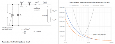
Note that the stator-to-stator panel capacitance is in parallel with the series network of mechanical and acoustical impedances.
But since all of those act thru the ESL motor, you can effectively turn them off with the polarizing voltage set to zero.
Taking an impedance measurement of the panel with polarizing voltage off will give you a curve representative of (Co + Cs). Now switch on the polarizing voltage and re-measure the impedance to add the mechanical and acoustic impedance contributions in parallel with (Co + Cs). Then, a little math removes the (Co + Cs) term leaving you with the impedance of the series Mechanical + Acoustic network. The minimum value occurring at resonance is the combined mechanical/acoustical damping resistance.
If you now added some damping mesh and re-measured the impedance you would get a new minimum value. The deference between the two minimums represents the resistance of the acoustic mesh referred to the electrical domain. A bit more math involving the transduction coefficient and diaphragm area and you have the value in Rayl.
Thanks for the comment, all good points and things I did no fully understand back when I performed the experiments. It also reminded me of another configuration I experimented with. Baffle wings were added to the stacked panel configuration such that the LF radiation impedance was the same for both configurations. The combined width with wings required to do this is similar to the width of the side by side configuration. The purpose of the test was to compare stacked vs side-by-side panels for the situation where they would produce the same LF SPL for the same diaphragm displacement. The question the comparison was trying to answer was(all other things being equal) if 2x Force applied to 1x Area , vs 1x Force applied to 2x Area had some inherent advantage in LF reproduction. There did not seem to be. Even with baffle wings helping out, the stacked configuration still did not show itself to be obviously superior in quality (ie dynamics and SPL) for LF only reproduction. The only place I think stacked panels makes sense for LF reproduction is when you are needing to keep the size small.The radiation impedance for two panels side by side is twice that for two stacked panels. That means the membrane displacement for a given pressure at the surface, is half, and the resonant frequency is lower (70%) due to increased air mass attached to the membrane. So the bass response is slightly better for panels side by side, and the membrane displacement less.
Last edited:
So with the polarizing voltage switched ON, the impedance curve is the grey (parabolic) or the orange curve?If you look at the ESL model in Post#237 and move all mechanical and acoustic parameters to the electrical domain, you get something like this.
View attachment 1050827
Note that the stator-to-stator panel capacitance is in parallel with the series network of mechanical and acoustical impedances.
But since all of those act thru the ESL motor, you can effectively turn them off with the polarizing voltage set to zero.
Taking an impedance measurement of the panel with polarizing voltage off will give you a curve representative of (Co + Cs). Now switch on the polarizing voltage and re-measure the impedance to add the mechanical and acoustic impedance contributions in parallel with (Co + Cs). Then, a little math removes the (Co + Cs) term leaving you with the impedance of the series Mechanical + Acoustic network. The minimum value occurring at resonance is the combined mechanical/acoustical damping resistance.
With the damping mesh installed on the stators, the minimum value is higher than it is represented in the grey curve that you have drawn, correct?If you now added some damping mesh and re-measured the impedance you would get a new minimum value. The deference between the two minimums represents the resistance of the acoustic mesh referred to the electrical domain. A bit more math involving the transduction coefficient and diaphragm area and you have the value in Rayl.
For a floor to ceiling line source, you would need an ESL roughly 2m wide to produce 125dB at 2m. This seems a bit physically imposing, so I reduced the width to 120cm for directivity evaluation. This would give you 120dB at 2m above a 200Hz crossover point.Yes I do, matter of fact 125dB at 2m for a line source floor to ceiling. the lowest is 200Hz
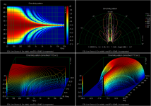
First, here is the directivity of the flat unsegmented 120cm wide floor-to-ceiling panel...definitely a small sweet spot.
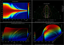
Symmetrically segmented panels driven by RC transmission lines as detailed in golfnut’s AES paper (https://www.aes.org/e-lib/browse.cfm?elib=14844) work best when the segmentation is extended lower in frequency than the ka=1 point of the panel(ie width = 1/3 wavelength). To achieve the 120dB down to 200Hz crossover point with panel width of 1.2m, segmentation stops about 1.5 octaves above ka=1...not optimal. You can see that dispersion is improved over the unsegmented panel, but not by a lot.
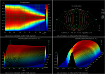
If you instead targeted 110dB, segmentation would be extended about 1.5 octaves below ka=1 and you can see the improvement in dispersion, and the characteristic smoothly changing directivity of the RC transmission line configuration. By 105dB dispersion is really starting to look nice. Quoting from the AES paper, "...there is a direct compromise between the angular extent of the high-frequency polar response...and the SPL"
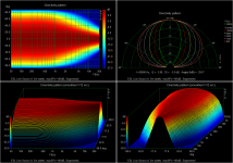
For high SPL designs, curved panels can also be used to increase dispersion. A 30deg curved panel gives nice coverage in a 30deg window with minimal ripples, although directive still necks down in the midrange. These dimensions are actually very similar to the original Martin Logan Statement. https://www.martinlogan.com/en/product/statement
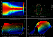
Another method used by SoundLab is to approximate a curved panel with 7 flat panels or facets. If this is used for a 30deg arc, you can see that below 10kHz there is very little difference between this and the curved panel. In my experience, constructing facetted panels is much easier than curved panels.
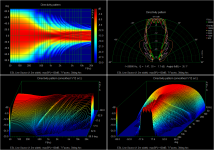
With the facetted configuration, you can also easily increase the arc from 30deg to 45, 60, or even 90deg.
But, you can see that by 60deg larger ripples in the response start to appear in the upper octaves.
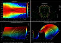
If you really need 120dB(or 125dB) I would recommend building something with a facetted configuration.
With a set of 7 floor-to-ceiling panels built, you could easily position them in a frame at various angles of arc between 30 and 90deg to see what works best for your application.
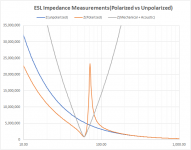
Polarizing switch ON and panel fully charged = orange curve (complex impedance = magnitude and phase)So with the polarizing voltage switched ON, the impedance curve is the grey (parabolic) or the orange curve?
Polarized switch OFF and panel fully discharged = blue curve (complex impedance = magnitude and phase)
The grey parabolic curve is calculated using equation for parallel impedances = 1/(1/orange - 1/blue)
Correct, the higher the mesh damping, the higher the minimum point of the grey curve. The plot I had posted was actually with mesh installed for a Q of about 2.With the damping mesh installed on the stators, the minimum value is higher than it is represented in the grey curve that you have drawn, correct?
Here is an example of what an undamped panel measurement set would look like.
Thank you bolserst for doing this simulation.For a floor to ceiling line source, you would need an ESL roughly 2m wide to produce 125dB at 2m. This seems a bit physically imposing, so I reduced the width to 120cm for directivity evaluation. This would give you 120dB at 2m above a 200Hz crossover point.
First, here is the directivity of the flat unsegmented 120cm wide floor-to-ceiling panel...definitely a small sweet spot.
View attachment 1050842
Symmetrically segmented panels driven by RC transmission lines as detailed in golfnut’s AES paper (https://www.aes.org/e-lib/browse.cfm?elib=14844) work best when the segmentation is extended lower in frequency than the ka=1 point of the panel(ie width = 1/3 wavelength). To achieve the 120dB down to 200Hz crossover point with panel width of 1.2m, segmentation stops about 1.5 octaves above ka=1...not optimal. You can see that dispersion is improved over the unsegmented panel, but not by a lot.
View attachment 1050846
My apology, I don't have a full understanding of segmented delay panels. How do you mean by 'the segmentation is extended lower in frequency than the ka=1 point' or 'segmentation stops about 1.5 octaves above ka=1'? And why is it not optimal when segmentation is above ka=1?
What is the cause of this 'neck down' in the midrange?If you instead targeted 110dB, segmentation would be extended about 1.5 octaves below ka=1 and you can see the improvement in dispersion, and the characteristic smoothly changing directivity of the RC transmission line configuration. By 105dB dispersion is really starting to look nice. Quoting from the AES paper, "...there is a direct compromise between the angular extent of the high-frequency polar response...and the SPL"
View attachment 1050847 View attachment 1050848
For high SPL designs, curved panels can also be used to increase dispersion. A 30deg curved panel gives nice coverage in a 30deg window with minimal ripples, although directive still necks down in the midrange. These dimensions are actually very similar to the original Martin Logan Statement. https://www.martinlogan.com/en/product/statement
View attachment 1050843
Another method used by SoundLab is to approximate a curved panel with 7 flat panels or facets. If this is used for a 30deg arc, you can see that below 10kHz there is very little difference between this and the curved panel. In my experience, constructing facetted panels is much easier than curved panels.
View attachment 1050844
Really nice set of plots Bolserst!
If anyone wants a copy of the paper at https://www.aes.org/e-lib/browse.cfm?elib=14844, send me a PM with your direct email address and I'll forward a copy.
If anyone wants a copy of the paper at https://www.aes.org/e-lib/browse.cfm?elib=14844, send me a PM with your direct email address and I'll forward a copy.
I already have it, thank you for the offer. Can you point out which section that covers 'extension of segmentation' in this context?Really nice set of plots Bolserst!
If anyone wants a copy of the paper at https://www.aes.org/e-lib/browse.cfm?elib=14844, send me a PM with your direct email address and I'll forward a copy.
Which mesh specifically do you use?Polarizing switch ON and panel fully charged = orange curve (complex impedance = magnitude and phase)
Polarized switch OFF and panel fully discharged = blue curve (complex impedance = magnitude and phase)
The grey parabolic curve is calculated using equation for parallel impedances = 1/(1/orange - 1/blue)
Correct, the higher the mesh damping, the higher the minimum point of the grey curve. The plot I had posted was actually with mesh installed for a Q of about 2.
Here is an example of what an undamped panel measurement set would look like.
View attachment 1050857
WYS - your question about extension of segmentation.... see the formular for the low cutoff frequency of the ESL, fL. Perhaps you mean a different question - how to avoid the ripples in the polar response by changing fL?
The answer relates to the other observation made about the tradeoff between the polar response and the SPL.
The RC transmission line is a series of cascaded RC low-pass filters - the R being the resistance between segments and C the capacitance of each stator segment. That means that the full voltage is applied only at the central segment of the ESL where the transformer is connected. The voltage at the other segments is attenuated by the RC filters - the further from the centre and the higher the frequency, the greater the attenuation.
So at very high frequencies, the panel only radiates significantly from the central segment (which is narrow and gives the ESL a wide dispersion), and at low frequencies, the signal propagates to the edge segments practically unattenuated, so that the whole panel radiates the bass signals.
If a large value is chosen for the R the exponential decay of the voltage as it propagates along the transmission line is rapid - so that the sound source appears narrow and the polar response is wide. If the R value is low, the exponential decay is less (segment voltages greater), the panel radiates more sound (SPL greater), but the polar response is narrower. Hence the trade off between a wide polar response and high SPL.
The nasty ripples in the polar response of some ESLs is caused by the large changes in the radiated sound over short distances. For example, with a large single segment ESL (bolserst's first figure) the edge of the ESL panel radiates full sound at all frequencies, but immediately beyond the edge of the ESL panel, there is no sound radiated. This gives rise to diffraction effects and the ripples in the polar response.
It turns out that if the RC transmission line attenuates the voltage fast enough as it propagates to the edge of the panel, then the diffraction effects are very small and there are no ripples in the polar response - as shown with bolserst's pictures. This requires the low cutoff frequency of the transmission line, fL (depends on R, C, and number of segments - see paper), to be less than the frequency where the radiation impedance of the panel suddenly changes (ka=1) - I'm struggling to remember, but I think for a line source, that frequency is approximately equal to 90 Hz divided by the width in metres. So very wide ESLs require a very low cutoff, and its not practical to build line source ESLs any wider than about 1 m, maybe a bit less.
Hopefully this is helpful - bit cryptic without the paper perhaps - had plans to write this up and describe the effect properly sometime.
Thank you for the excellent explanation. Give me sometime to finish reading your AES paper, I’m catching up.
Thanks for this Steve.If you look at the ESL model in Post#237 and move all mechanical and acoustic parameters to the electrical domain, you get something like
....
The minimum value occurring at resonance is the combined mechanical/acoustical damping resistance.
So not quite as simple as EML as you need to measure Complex Z. For EML, you just need an oscillator and voltmeter flat over the frequencies of interest.
But all modern measurement methods today would determine 'impulse response' and use FFTs so you have all the info available to get your grey 'parabolic' curve of resistance.
The good news is that important stuff like Co and alpha can be calculated very simply and accurately.
If I may ask you to enlighten my single remaining brain cell further ...
- alpha is the ELS Force constant ie Newtons/Volt
- but what is Cme alpha^2 = -Co
I grovel at your feet Oh Guru bolserst 🙂
Since golfnut addressed your question in detail, I will only add that there is a spreadsheet posted for download that performs the calculations from the AES paper....I don't have a full understanding of segmented delay panels. How do you mean by 'the segmentation is extended lower in frequency than the ka=1 point' or 'segmentation stops about 1.5 octaves above ka=1'? And why is it not optimal when segmentation is above ka=1?
https://www.diyaudio.com/community/threads/experiences-with-esl-directivity.48120/post-5441902
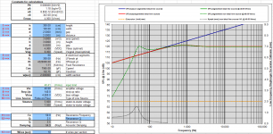
The lower frequency extent of the segmentation is input parameter #6, fL. You will notice as you lower fL, the SPL of the whole response lowers.
The only thing missing is the calculation for frequency at which ka=1.
f(ka=1) = c/(width*pi) = 109.2/width, where width is in meters
Here is an example with parameters set for your 120dB line source.
It results from the wavelength of sound relative to the width of the panel and the dimensions of the arc. The polar response necks down when the wavelength becomes large relative to the arc dimensions but still small relative to the width (ie panel starts to behave like it is flat not curved). Continuing to go down in frequency, once the wavelength becomes larger relative to the panel width the polar response reverts to the classic dipole.What is the cause of this 'neck down' in the midrange?
Last edited:
It was some mesh with acoustic resistance of 70 Rayl.Which mesh specifically do you use?
Indeed. The fact that the stator-to-stator capacitance is always in parallel with any impedance measurement requires Complex Z so you can mathematically remove it from the measurement.So not quite as simple as EML as you need to measure Complex Z. For EML, you just need an oscillator and voltmeter flat over the frequencies of interest.
Cme is the negative compliance term. When the polarizing voltage of a constant charge ESL is turned on, part of the force equation includes a term that is proportional to the diaphragm displacement…ie a spring with negative stiffness. Its magnitude is always equal to the driven panel capacitance, Co, times the square of the transduction coefficient. For stability reason, you need to tension the diaphragm so that it's mechanical stiffness is at least as large as the Cme term. Usually it is best to set it > 2 or 3 times that to ensure stability with varying bias voltages, temperatures, and LF acoustic environment.If I may ask you to enlighten my single remaining brain cell further ...
- alpha is the ELS Force constant ie Newtons/Volt
- but what is Cme alpha^2 = -Co
For more details, refer to Sections 2.2.2 thru 2.2.7 in the Baxandall ESL chapter.
Du..uh! I should know this from pretending to design condensor mike for Calrec. It's the 'diaphragm collapse' factor. 😱Cme is the negative compliance term. When the polarizing voltage of a constant charge ESL is turned on, part of the force equation includes a term that is proportional to the diaphragm displacement…ie a spring with negative stiffness.
I know it in slightly more complex single sided form.
Thanks for this Steve .. and for the reference to Great Guru Baxandall
- Home
- Loudspeakers
- Planars & Exotics
- Electrostats vs conventional drivers
