Hello,
A while back I build a Salas 6v6 preamp, and combined it with a low gain version of Hypex Ncore power amp, and I really love it. I like this hybrid combination despite the purists from either camp.
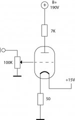
This time I have a pair of 71a tubes, a pair of Neurochrome Modulus-86 boards, a Vicor PSU a bunch of DC-DC modules, and a gutted old Stromberg Carlson chassis. I plan to make an integrated amp out of it all. I don't need more than 3-6db gain from the 71a's, so I figure a simple resistor loaded tube stage should be fine. I'm not really an expert on calculating load lines and all the details, but I cobbled together this incredibly basic input stage from operating points mentioned here, here, and here. I have an isolated 190V on hand from the DC-DC convertors, although I can trim the voltage down a bit.
Thanks!
A while back I build a Salas 6v6 preamp, and combined it with a low gain version of Hypex Ncore power amp, and I really love it. I like this hybrid combination despite the purists from either camp.
This time I have a pair of 71a tubes, a pair of Neurochrome Modulus-86 boards, a Vicor PSU a bunch of DC-DC modules, and a gutted old Stromberg Carlson chassis. I plan to make an integrated amp out of it all. I don't need more than 3-6db gain from the 71a's, so I figure a simple resistor loaded tube stage should be fine. I'm not really an expert on calculating load lines and all the details, but I cobbled together this incredibly basic input stage from operating points mentioned here, here, and here. I have an isolated 190V on hand from the DC-DC convertors, although I can trim the voltage down a bit.
- Does this basic schematic look ok, with 7K?
- What would the output impedance of the preamp stage be?
- Also, Ale has the grid biased to -10V, but the data sheet mentions -27V, as does the other DIYA thread I referenced. Could someone clarify what is optimum?
Thanks!
Attachments
Last edited:
You need 5volts for the filament and in turn thf filament requires elevating to coinside with the performance you want.
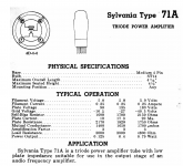
Bearing in mind this valve has an amplification factor of a mere 3, is it worth using for this purpose.
The filament voltage must not be used with a heater load resistor as you have drawn!
Data sheet attached for you to see what is required.
Bearing in mind this valve has an amplification factor of a mere 3, is it worth using for this purpose.
The filament voltage must not be used with a heater load resistor as you have drawn!
Data sheet attached for you to see what is required.
Attachments
Ok, please help me to understand. When using a CC supply to power the filaments as Ale and others do, is it not basically 15V dropping 10V across the filament resistor, giving it the 5V across the filament itself and 10V elevation it needs?You need 5volts for the filament and in turn thf filament requires elevating to coinside with the performance you want.
Bearing in mind this valve has an amplification factor of a mere 3, is it worth using for this purpose.
The filament voltage must not be used with a heater load resistor as you have drawn!
Data sheet attached for you to see what is required.
This tube requires 0.25A filament current (if filament voltage is 5V).
50R*0.25A= 12.5V
12.5V +5V (filament)= 17.5V DC voltage, instead of +15V.
50R*0.25A= 12.5V
12.5V +5V (filament)= 17.5V DC voltage, instead of +15V.
Ok thanks. I can lower it to 17.5V no big deal. My range on the DC-DC converter is 12-24V. Or I can change the filament resistor slightly as well. Otherwise it looks right, correct? John Snell seemed to throw cold water.This tube requires 0.25A filament current (if filament voltage is 5V).
50R*0.25A= 12.5V
12.5V +5V (filament)= 17.5V DC voltage, instead of +15V.
Ok thanks. I can change it to 17.5V no big deal. 15V was for a slightly starved filament as per one of Ale's post. My range on the DC-DC converter is 12-24V. Or I can change the filament resistor slightly as well. Otherwise it looks right, correct? John Snell seemed to throw cold water.
Last edited:
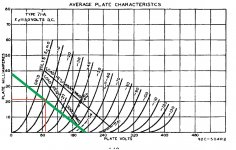
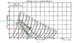
According to the curves, your load line would be like this when B+=190V and Anode Resistance=7K.
You can choose any point you like on the loadline to decide the grid bias.
Plate current and DC plate voltage would be fixed when the grid bias was decided.
The -27V bias in the datasheet is a reference operating point when using the tube as a power output stage with output transformer coupled.
But your schemetic is a voltage amplification stage with resistor as anode load.
They are totoally different. Just put aside the typical operating point in the datasheet.
The output impedance is the parallel value of Anode resistor, which is 7K now and 71A's plate resistance (About 2K when Vg=-10V and Ia=16mA).
So you'll get 1.56K here.
If the output capacitor is not so large, the impedance of the capacitor should be added to the value above.
And here's something you should notice. The filament of the tubes should always be driven with a certain voltage instead of a certain current. When using filament CCS, you should adjust the current to get an accurate voltage across the filament when the tube is fully heated. It's the same here. If you want to use -10V bias, since the filament current is about 0.25A. The resistor should be about 40ohms. Don't turn on the plate supply, heat up the tube with your DC supply, and trim it until the voltage across the filament is accurately 5V for at least 10 minutes.
Thank you so much KoitoYuu! I feel like I've read about load lines a million times, but this is now very clear. It now seems like a 5K load resistor would be better, based on Ale's experience saying 20-25ma is when the 71a sounds it best.
So, 190/5K = 38ma = Y-axis
190 = X axis
-10 bias = 20-22ma
Correct?
So, 190/5K = 38ma = Y-axis
190 = X axis
-10 bias = 20-22ma
Correct?
Attachments
Yeah, that's it.Thank you so much KoitoYuu! I feel like I've read about load lines a million times, but this is now very clear. It now seems like a 5K load resistor would be better, based on Ale's experience saying 20-25ma is when the 71a sounds it best.
So, 190/5K = 38ma = Y-axis
190 = X axis
-10 bias = 20-22ma
Correct?
And higher plate current always means lower plate resistance at the same time.
But lower anode load resistance also means higher distoration. I think the best way to meet the plate current of 20-25mA is raising the HV supply.
I wonder if using plate chokes is an option for you? The power supply section only need to provide DC plate voltage. All AC voltage would be from the inductor. So you can meet lower total supply voltage, higher current and higher load resistance at the same time. For example, LL1668 25mA. It has 100H which means you will get 12.6Kohms at 20Hz, and the load line would be almost level from 100Hz to 10KHz. A level loadline will maximize the linearity of the tube.
Using Gyrator or Constant Current Source as anode load will have similar effect on maximizing the linearity. I guess Ale would prefer Gyrator or CCS. 😏
With the DC switchers I have 190 is about as high as I can go. A choke sounds like a great idea as long as I can fit it in my case.
I’ll probably try the resistor first and do some listening and measuring tests and see how it goes. Too simple not to try.
I also have quite a few 10m45s CCS chips left over from a Tubelab build from many years ago.
thanks for the tips and suggestions!
I’ll probably try the resistor first and do some listening and measuring tests and see how it goes. Too simple not to try.
I also have quite a few 10m45s CCS chips left over from a Tubelab build from many years ago.
thanks for the tips and suggestions!
For 71A with Filament bias, the output voltage will need to be ca. 18-20V, allowing for usual range of anode current, and filament current.Ok thanks. I can lower it to 17.5V no big deal. My range on the DC-DC converter is 12-24V. Or I can change the filament resistor slightly as well. Otherwise it looks right, correct? John Snell seemed to throw cold water.
With 50Ω of filament bias resistor, the gm of the 71A will drop from 1.7mA/V to ca. 1.57mA/V. That's OK.
Typical DC-DC modules (especially from Ali or ebay) have plenty of switching noise (may not matter, depending on the whole system) and also, high baseband noise (Audio frequency). With and unbypassed 50Ω F/B resistor, don't be surprised to find hiss in the speaker, if you use this in a preamp stage.
Thanks Rod. Good info. The DC DC converters that I mentioned in the first post are these in conjunction with a ripple attenuator here. I've measured them before, and under load, switching frequency is around 300kHz, and seem to remember in the low mv area. We'll see how they work out. Will keep you posted.For 71A with Filament bias, the output voltage will need to be ca. 18-20V, allowing for usual range of anode current, and filament current.
With 50Ω of filament bias resistor, the gm of the 71A will drop from 1.7mA/V to ca. 1.57mA/V. That's OK.
Typical DC-DC modules (especially from Ali or ebay) have plenty of switching noise (may not matter, depending on the whole system) and also, high baseband noise (Audio frequency). With and unbypassed 50Ω F/B resistor, don't be surprised to find hiss in the speaker, if you use this in a preamp stage.
So, I made some headway! I have a ground loop somewhere, because when I touch the case 60Hz goes down by 10dB. I think I might know what it is, will investigate later.
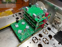
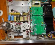
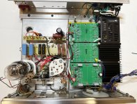
So, I used some Vicor DC DC switchers, in high-voltage arrangement as here. And I made some PCB shields as per this design guide. Made a lot of mistakes on the PCB, so had to drill out holes, run wires. Oh, well made it work.
Load line and calculations worked exactly as planned! 246mA on the filaments, 4.7K anode resistor yielded 20ma on the tube. Running B+ around 220V, which is as high as want to go with the switchers. THD is quite good at -80db for 2H. After running for 30m, 2H goes down to -85dB.
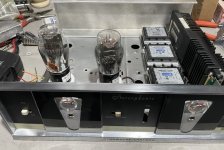
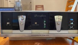
Repurposing a Stromberg chassis. Turned out to be way too much hand machining with a dremel.
Left some space in the back for a solid state power amp section. I plan to use a Neurochrome module.
Anyway, here are a few pics from a productive day. Gotta get the noise down, will work on later.
So, I used some Vicor DC DC switchers, in high-voltage arrangement as here. And I made some PCB shields as per this design guide. Made a lot of mistakes on the PCB, so had to drill out holes, run wires. Oh, well made it work.
Load line and calculations worked exactly as planned! 246mA on the filaments, 4.7K anode resistor yielded 20ma on the tube. Running B+ around 220V, which is as high as want to go with the switchers. THD is quite good at -80db for 2H. After running for 30m, 2H goes down to -85dB.
Repurposing a Stromberg chassis. Turned out to be way too much hand machining with a dremel.
Left some space in the back for a solid state power amp section. I plan to use a Neurochrome module.
Anyway, here are a few pics from a productive day. Gotta get the noise down, will work on later.
Attachments
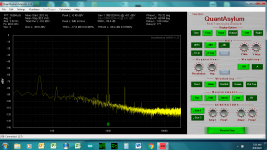
So, I completely rewired the ground scheme. I think it is a much better scheme now. I plugged it in, and guess what? Exactly no difference than before. 60Hz at -60dBV, and 120 at -80dBV. Touching the chassis, noise goes down by a full 20dB. I realized it's some sort of grounding thing, but I am 100% positive I grounded everything to the case (using a bus). DC power supply is earthed as well, with a star washer.
I suspected the outlet, since I live in an old house. It sounded to me as if the outlet was not earthed correctly.
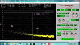
I moved the amp and analyzer to the kitchen which was completely renovated 3 years ago, and which I know for a fact was wired properly. Much better results! I'm actually quite impressed by the performance of these old tubes. See attached.
I don't intend to use the preamp on an outlet that is not properly earthed, but the question is, is it a hazard to do so? Here I am using a SMPS, and some DC DC converters (compatible, from the same company). What about in this case? Here is the link to the the SMPS.
I suspected the outlet, since I live in an old house. It sounded to me as if the outlet was not earthed correctly.
I moved the amp and analyzer to the kitchen which was completely renovated 3 years ago, and which I know for a fact was wired properly. Much better results! I'm actually quite impressed by the performance of these old tubes. See attached.
I don't intend to use the preamp on an outlet that is not properly earthed, but the question is, is it a hazard to do so? Here I am using a SMPS, and some DC DC converters (compatible, from the same company). What about in this case? Here is the link to the the SMPS.
Attachments
Last edited:
I'm going to answer my own question and say it is unwise, and unsafe to use an a poorly grounded or ungrounded receptacle for such a device. I have a new found interest to check all the receptacles in my house now. Some appear to be grounded properly, and some not.
71a is a DHT tube, so EACH filament DC-DC converter AND its AC-DC raw supply (separated raw supply for each tube) PSU must be floating!
Each of them must be isolated from other DC-DC converter, from chassis and from safety ground of line power.
Is AC-DC converter has safety ground point?
Each of them must be isolated from other DC-DC converter, from chassis and from safety ground of line power.
Is AC-DC converter has safety ground point?
I will draw it up later, but here’s how it’s wired.
The main smps (AC in/24VDC out) is bonded to the chassis on the AC side with its earth wire connected near the 3 prong IEC fused inlet as it should be. It’s 24VDC output is floating, and left floating.
This floating 24V is connected to the input side of 3 groups of DC DC converters (B+, Filament Left, Filament Right). These points are all floating, and all converters are isolated from each other. The converters themselves are fully isolated types, see data sheet.
On the converter output side, the 0V from the B+ converters is connected to earth ground. The 0V from the (2) isolated DC converters (trimmed to 19V out) of Filament Left and Filament Right are also connected to earth at the same point. This is also the base of each individual 56 ohm filament resistor.
The output RCA jack is isolated from the chassis via plastic washers and an o-ring and then the rca output grounds are connected to earth ground at a point on the bus. Output itself is through a 2.2uF film cap and 300k drain resistor to ground.
The RCA input jack is wired similarly to the output, except this input ground is connected to the ground bus through a 100 ohm || 100nF cap. (Not sure this was necessary, but when I redid all the grounding I added this).
Last edited:
If the "earth ground" means third AC line input point of AC/DC converter, it's wrong. The safety earth wire connecting to the metal case is necessary, but it's NOT grounding point!The main smps (AC in/24VDC out) is bonded to the chassis on the AC side with its earth wire connected near the 3 prong IEC fused inlet as it should be....
On the converter output side, the 0V from the B+ converters is connected to earth ground. The 0V from the (2) isolated DC converters (trimmed to 19V out) of Filament Left and Filament Right are also connected to earth at the same point. This is also the base of each individual 56 ohm filament resistor.
Use local grounding bus (or star grounding point) for EACH channel, connect there DC-DC converter "cold" output point and all component (resistors, capacitors, RAC cold wires -even via R//C- etc.) which are "grounded" within this channel.
Connect each channel grounding point (bus or star grounding point) to -isolated- common grounding point.
Tie this common grounding point via 10R resistor (or hum killer like in attached sample -left bottom side-) to safety ground point.


BTW these old DHT tubes are would notoriously sensitive to radiated disturbances, so if you wraps it with -grounded- aluminium folie and hum gone, must to shield tubes too.
Last edited:
If the "earth ground" means third AC line input point of AC/DC converter, it's wrong. The safety earth wire connecting to the metal case is necessary, but it's NOT grounding point!
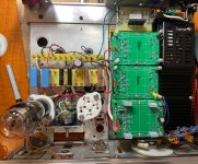
Sorry, I could have been clearer. I did not connect all the star grounding points of the amplifier to the point where IEC inlet/3rd AC line input earth ground connects to the chassis.
I connected a 25cm long 14 AWG bare copper wire that does connect to that point, but it bisects the chassis between the PSU side and amplification side. See picture in post 14. I tapped this bus at a few points for filament "cold" output , B+ "cold" output, as well as the inputs and outputs.
I am aware of the 10R || 100nF || diode bridge as the isolator between earth and circuit ground, but my understanding is that it is optional. I just felt safer without it, and in my case it made no difference in the measurements,. Originally I had it done that way, but when I cleaned up the grounding as per post 14 I removed it, and just raised the input with a 100R||100nF which as I understand it is also an option and perfectly safe. Is that a bad idea? I did it with a class D amplifier one time, as per a Hypex application note, and it made a massive difference. Btw, did you see the measurement in post 14? Some hum at 60Hz, -78db with ref to 1V out, but other than that, noise is relatively low. What's your opinion?
I do not have a ground bus for each channel, and that could be an improvement, so thanks for the suggestion.
To be clear, are you saying that how I wired things is unsafe, or rather that it can be improved? It's hard to tell with everything in bold with exclamation points. I thought AndrewT came back from beyond for a second

Last edited:
You connected line power safety earth to chassis, so for life protection it's OK.
IMHO the long ground wire, where components grounding has random connection points, not optimal.
Sooner I will draw sample grounding scheme.
BTW are you tried four wire (+Out, +S, -Out, -S) method?
Remote sensing on the load (for example preamp channel B+ tied to +Out, +S, and preamp channel GND to -Out, -S) gives better regulation.
-78dB hum component not too bad, but if you look carefully it's interfering with 1kHz signal, and make +/- 60Hz sidebands (modulation) at -103dB.
Are you sure, that switching PSUs metal part not connected to case? I saw there metal threaded rods.
- Home
- Amplifiers
- Tubes / Valves
- 71A preamp