Two tests were performed on each tube type (12GN7 and 12HL7).
1. Distortion with UPT-2 as a plate load ( Spec 29H at 110mA)
2. Distortion with cascaded DN2450 Current Source
Test 1 UBT-2 plate load
Va = 250V
Ik=10.1mA Rk 344 Ohms w/ 1000uF cap in parallel
Plate load UPB2 with a 220 ohm resistor on the 8 ohm, output giving a reflected load of 132K in parallel with a resistor divider consisting of 100K and a 10K pot capacitively coupled to the sound card input.
The total effective load is thus 110K in parallel with 132K or approximately 60K This is probably low compared to most 300B Grid resistors (for cathode bias, but probably close for fixed bias), however I was limited by the UBT–2 as a plate load and the sound card input.
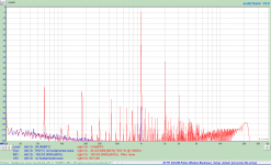
12GN7 (This was the worst of the 20 tubes I have)
Vo 70.4 Vrms
Vi 1.84 V rms
Gain 38.3
THD = 0.617
1. Distortion with UPT-2 as a plate load ( Spec 29H at 110mA)
2. Distortion with cascaded DN2450 Current Source
Test 1 UBT-2 plate load
Va = 250V
Ik=10.1mA Rk 344 Ohms w/ 1000uF cap in parallel
Plate load UPB2 with a 220 ohm resistor on the 8 ohm, output giving a reflected load of 132K in parallel with a resistor divider consisting of 100K and a 10K pot capacitively coupled to the sound card input.
The total effective load is thus 110K in parallel with 132K or approximately 60K This is probably low compared to most 300B Grid resistors (for cathode bias, but probably close for fixed bias), however I was limited by the UBT–2 as a plate load and the sound card input.
12GN7 (This was the worst of the 20 tubes I have)
Vo 70.4 Vrms
Vi 1.84 V rms
Gain 38.3
THD = 0.617
Attachments

Last edited:
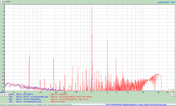
Test 2 Cascade DN2540 plate load
Va = 230V (Cascode adjusted with Rk kept constant)
Ik=10.3mA Rk 344 Ohms w/ 1000uF cap in parallel
Plate load equals capacitively coupled gate input and G-S resistor which for a source follower is in the 10s of meg ohms.This buffers the resistor divider consisting of the 100K resistor and a 10K pot capacitively coupled to the sound card input.
12GN7
Vo = 70.4 V rms
Vi = 1.80 V rms
Mu = 39.1
THD = 0.532
Attachments
I made an interesting observation on the 12GN7 when driving the choke load. Somewhere around 14 ma the tube started running away. The 12GN7 is not a sweep tube, and has a Vg2 rating of 300V. As long as I kept the current around 10-12mA I had no issues.
The advantage I see to the choke load is it requires much less voltage than the CCS loaded topology. This is because the choke can swing nearly twice the anode supply voltage.
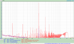
Both tubes show dominant 2nd harmonic with much lower 3rd and fourth. Harmonics beyond fourth were below the noise level of my test system and at least 100dB below the fundimental.
The advantage I see to the choke load is it requires much less voltage than the CCS loaded topology. This is because the choke can swing nearly twice the anode supply voltage.
Both tubes show dominant 2nd harmonic with much lower 3rd and fourth. Harmonics beyond fourth were below the noise level of my test system and at least 100dB below the fundimental.
Last edited:
Sorry to drag up this old thread. I'm working on a push-pull amp based on the 5-20 topology. I have some very nice 6SN7 tubes for the phase inverter so I looked to the Citation V 6CG7 tube phase inverter as a guide. According to the schematic, there's 150V for the tail, and with a 27k resistor, there's 5.56mA of total current through both triodes. When I drew the load line according to Merlin, each triode will draw around 5.2mA, so the tail resistor should be 1/2 of the stated value. Is the schematic off, or is there something wrong with my understanding of Merlin's guide?
According to my files, a 6FQ7 used for a phase inverter with a 230V B+ typically uses a 27K at the plate and cathode.
The Cit. V‘s front 12BY7 is direct coupled (without capacitor) to the 6CG7 phase inverter (PI). I suspect that this design choice constrains the operating conditions on the PI and may have led to the adoption of a less than ideal operating point. However, the Cit V sounds marvelous, so, we cannot really fault the recipe.Sorry to drag up this old thread. I'm working on a push-pull amp based on the 5-20 topology. I have some very nice 6SN7 tubes for the phase inverter so I looked to the Citation V 6CG7 tube phase inverter as a guide. According to the schematic, there's 150V for the tail, and with a 27k resistor, there's 5.56mA of total current through both triodes. When I drew the load line according to Merlin, each triode will draw around 5.2mA, so the tail resistor should be 1/2 of the stated value. Is the schematic off, or is there something wrong with my understanding of Merlin's guide?
Check the EICO HF87/89 schematics. They also use 6SN7 PIs in the Mullard topology and are also direct coupled, albeit to a 12ax7, and indeed use 18k tail resistors, with 28/33k plate resistors. Good luck.
The Eico ST-70 uses 6SN7 as the LTP as well. And with an 18k tail resistor. I have replaced the resistor with a CCS in the past and that also works well but you have to match the plate loads this way.
John
John
I drew up the Eico loadlines, and they are closer to theory. The tail resistor should be around 14k. Trash the paper and pencil (or MS Paint 😀). Time to breadboard and bumblefudge my way into a workable solution.

you may also want to try the 6SL7 long tail pair instead of the 6sn7, i made such an amp, that used the 5814 as voltage amp in the Mullard 5-20 type topology.....
So with B+ of 400V, and 130V for the tail, I drew up the load line using the 6SL7 with 100k plate resistor. The tail resistor worked out to be 56k. That's basically a CCS 😛.

What would be the advantage of using 6SL7 over 6SN7?you may also want to try the 6SL7 long tail pair instead of the 6sn7, i made such an amp, that used the 5814 as voltage amp in the Mullard 5-20 type topology.....
it has less voltage swing capability, and its plate resistance is higher... 🙂What would be the advantage of using 6SL7 over 6SN7?
cheers,
Douglas
I hope he is okay, he is extremely knowledgeable and a gentleman. I don't know if he would remember me, but please pass along my best wishes.
Douglas, if you have his phone no. please call him and add my best wishes to the sentiments anatech expresssed. I have sent him a PM couple of weeks ago but did not receive a reply.
What would be the advantage of using 6SL7 over 6SN7?
remember that the original Mullard 5-20 used the 12at7 as long tail pair, so that i merely switch to an octal sibling. but frankly o liked the sound better, i do not imply superiority over the 6sn7 but just that i liked it when i tried it...
and since i do not need the gain of the ef86, i went for the 5814 with lower gain..
some news ?Question for Douglas, Tony, or anyone who might know him - I have not seen any posts from Eli Duttman since late last year. Wondered if he is OK?
P.S. since Eli is a big fan of Cit V I guess it is OK to ask in this thread.
- Home
- Amplifiers
- Tubes / Valves
- HK Citation V schematic?