That's why voltage used to be called EMF -- "Electro-Motive Force" --' it's what drives current.Current depends of voltage. Ib depends from Vbe. That's why bipolar transistors are voltage controlled devices, they are transconductors like other active amplifiers devices, tubes, FETs.
Most of your questions have been answered. The bipolar transistor is a voltage-controlled device, because the base-emitter diode follows an electrostatic potential inside the device as all diodes do. Basic text books will all state that a PN junction in equilibrium has a depletion region between the P and the N region due to the opposing forces of diffusion where electrons try to diffuse into the p and holes from the p into the n. In so doing they generate a localised electric field where they once were. This field is measured in volts and pulls electrons and holes back into their home ground. External volts, like your base-emitter voltage, alters the potential, so depending on which way round the depletion region will increase or decrease. If it decreases, the bias is forward. That is electrostatics, just dependent on volts. The current flow increases because the electrostatic force pulling electrons back into the n region and holes into the p is reduced - that is to say, diffusion whcih wants to happen is opposed less. Bipolars are often considered as current amplifiers because the actual base current flow is much lower than the emitter current, most of which ends up in the collector. But applying a current into the base simply sets the voltage until the base current matches the input.
In a real situation of course the applied volts and resulting currents are always power, as PRR suggests. And current flow across a base is charge, so charge is also a reasonable consideration.
As others have said in the emitter follower as the base voltage is applied the emitter voltage increases. The output voltage rises. A positive going signal into an NPN emitter turns it off with respect to the base. No other conclusion is possible than that being negative feedback.
Your OP states that beta is specifiable, but both beta and the internal emitter resistance Re are both dependent on the current. As Ian H pposted a Gummel plot, you can see that at the extremes the two lines converge and that means the gain falls. The diagram seems a little idealised with a wide current range over which the collector and base current lines are parallel, but modern transistors do have a reasonably good "linear" gain range.
In the case of an emitter follower, 100% feedback does not guarantee zero distortion. The output voltage is always lower than the input as the bipolar base emitter voltage changes with current- which is apart from the normal Vbe of around 0.65V or so. If you have an EF circuit with the transistor running at 5mA say with a 1k load (5V drop) then a 1V AC input pushes the base up and down by +/-1.4+ volts. The load current changes from about 3.6 to 6.4mA or more if an additional AC coupled load is present, and the change in the base-emitter voltage will be in the order of +6mV and -8mV. Not linear.
And your transformer circuit - it depends. Nothing will happen at DC in the output but if there is any drive to the transistor at all it sees a short and may go bang. As far as A.C. is concerned you can put in an equivalent load resistance and that shows it will behave as though it were a resistor i.e. yes it is negative feedback again. But transformer loads need careful handling as distortion can increase rapidly if the core gets close to saturating.

Veryb good John. I would like to add that 100% fb does not guarantee low distortion, it all depends on the available gain the fb has to 'work with'.
In a BJT if you take the (current) gain as the Hfe, you can expect that an emitter follower has about Hfe distortion reduction. However, the non-degenerated BJT is pretty non-linear so even with Hfe to work with, the distortion will be a far cry from zero.
Jan
In a BJT if you take the (current) gain as the Hfe, you can expect that an emitter follower has about Hfe distortion reduction. However, the non-degenerated BJT is pretty non-linear so even with Hfe to work with, the distortion will be a far cry from zero.
Jan
So I'm wondering, what kind of distortion does an emitter follower suffer from? harmonic distortion? noise? intermodulation distortion?Veryb good John. I would like to add that 100% fb does not guarantee low distortion, it all depends on the available gain the fb has to 'work with'.
In a BJT if you take the (current) gain as the Hfe, you can expect that an emitter follower has about Hfe distortion reduction. However, the non-degenerated BJT is pretty non-linear so even with Hfe to work with, the distortion will be a far cry from zero.
Jan
@IanHegglun @Mark Tillotson
Noise is not distortion. And there is only one form of distortion here, non-linear distortion. It can be measured by looking at the harmonics of a single signal, or it can be measured by using more than one signal and looking at the intermodulation. But that's just different ways of looking at same the basic non-linearity.
I don't know from the top of my head what form the non-linearity of an emitter follower has.
Jan
I don't know from the top of my head what form the non-linearity of an emitter follower has.
Jan
Voltage-controlled or Current-controlled? It has been convincingly argued that vacuum tubes, BJTs, and FETs are all Charge controlled. This truth is muddled in BJTs because to get maximum gain they leak horribly in the (uninsulated) Base.
Amplifying Devices and Low-pass Amplifier Design, Daryl E. Hooper and E. M. Cherry
https://worldradiohistory.com/BOOKSHELF-ARH/Technology/Amplifying-Devices-andLow-Pass-Amplifier Design-Cherry-Hooper-1968-RR.pdf
Thanks PRR, very interesting.
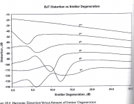
Found this in my files. Shows how the distortion of an emitter follower varies with the amount of emitter degeneration. No details about the circuit though, but I think it is from Bob Cordell's book, which I haven't here at the moment..
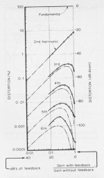
The graphs shows the familiar shapes: if you use just a little feedback, the main harmonic will be lowered but some higher harmonics may actually increase.
That's why those in the know say: if you need fb, use lots of it, as much as you can. Then all harmonics will decrease.
Jan
The graphs shows the familiar shapes: if you use just a little feedback, the main harmonic will be lowered but some higher harmonics may actually increase.
That's why those in the know say: if you need fb, use lots of it, as much as you can. Then all harmonics will decrease.
Jan
Attachments
Excuse me but doesn't the emitter follower has always 100% negative feedback in voltage? How you can choose the amount of the emitter degeneration?Found this in my files. Shows how the distortion of an emitter follower varies with the amount of emitter degeneration. No details about the circuit though, but I think it is from Bob Cordell's book, which I haven't here at the moment..
The graphs shows the familiar shapes: if you use just a little feedback, the main harmonic will be lowered but some higher harmonics may actually increase.
That's why those in the know say: if you need fb, use lots of it, as much as you can. Then all harmonics will decrease.
Jan
From what I know, you can only do this on a common emitter stage.
Yes, I think post 47 is common emitter, post 48 is push-pull emitter follower, post 49 is common source.
You can use a gain stage, picking off the signal at the collector resistor, and then use an emitter resistor to add degeneration and the gain will be lower (roughly Rc/Re). So from the point of view of the output (the collector) you can increase feedback by increasing the emitter resistor as a fraction of the collector resistor.Excuse me but doesn't the emitter follower has always 100% negative feedback in voltage? How you can choose the amount of the emitter degeneration?
From what I know, you can only do this on a common emitter stage.
Jan
A property common of active amplifying devices, tubes and transistors, is that they have an electrode which imperfectly copies the voltage variations of the input electrode. In amplifying circuits, its effect can be seen as soon as this electrode is separated from ground by a load. What can then mean 100% negative feedback ?doesn't the emitter follower has always 100% negative feedback in voltage?
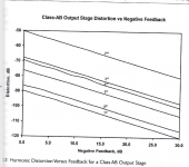
Peter Baxandall used a gain stage (Common Emitter).

His article is available here https://hifisonix.com/audio-power-a...ndall/baxandall_audio-power-amplifier-design/ and go to Part 6 (a download is easier to read). The transistor is Common Emitter for AC. The base effectively see 1k at AC - effectively adds 1k/(Beta+1) in series with the transistors re. The re~Vt/Ic=26mV/1.5mA=17 ohms. His Beta is 580, So add another 2 ohms to re giving about 20 ohms. The gm=1/re = 50mA/V. The available loop gain is gmxRL = 50m x 3k3 = 165 or 44dB (neglecting Early effect).
He varies the amount of feedback from 0dB (no feedback) to 40dB (almost max available) using the feedback pot.
With full feedback the jig would give the amount of feedback that an emitter follower would give which is pretty close to the 40dB mark on his plot Fig 2 (see Post 49 above). My Post 22 jig showed an emitter follower gives exactly the same distortion as a common emitter stage with 100% feedback. The feedback depth of an emitter follower in dB is 20 Log10(1+gmRe) where gm is the Common Emitter transconductance at the DC operating point. And the gm can be calculated as shown above.
Typically the feedback depth of an emitter follower is 30dB to 40dB. This is more than enough feedback to get over the "enough feedback" requirement for re-entrant distortion to be a non-issue in our amps, as shown in Bob's plot Post 48 above.
Last edited:
- Home
- Amplifiers
- Solid State
- The Emitter Follower Enigma