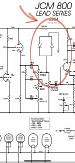
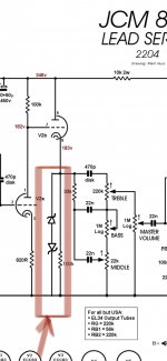
Hello ,, I have a clone of jcm 800 2204 and I want to add more gain .. and I see the 2205 and 2210 jcm800 have diode clipping , so I want to add some diodes … check please my schematic .. is correct to make this with 2x 1N4148 silicon ? Thank you . The first pic is original schem. And the 2nd is my thought. Is correct ?
Attachments
Would work, but you may want 2 or more diodes in series instead of just one per polarity.
Depends on the source, pots, and gain structure.
Depends on the source, pots, and gain structure.
Plig, you know the drill, 😉 this should be in the Musical Instruments section, not here.
As a side note, diodes do not provide any gain.
As a side note, diodes do not provide any gain.
I’m trying 2x 1N4148 like my draw and I hear some gain more but the volume drops and I hear noises and buzz …. I search a little bit and I found some sites with layouts from amps with clippings , and most use zener diodes , so I add 2x zener 15volt in series ( -+ +- Ground ) and the volume drops a little bit and the gain increase well and also I don’t hear noises .. may I make a lot of test to found my choice . One question : I use 15 volt zener if I change this zener with 20volt I take more gain ? Right ?!
Attachments
Wrong.I use 15 volt zener if I change this zener with 20volt I take more gain ? Right ?!
Diodes-do-NOT-provide-gain.
Only clipping, at different levels, completely different thing.
And why are you still here?
Click the black "report" circle bottom left and ask for this thread be moved to Musical Instrument Amps.
 thread moved
I ask for moving the thread .. I talking only for CLIPPING DIODES !!! why are you stick with the words ? I WANT TO MAKE DIODES CLIPPING TO MAKE MY SIGNAL MORE AGGRESIVE AND SATURATED… that’s it ….I take the idea from hereWrong.
Diodes-do-NOT-provide-gain.
Only clipping, at different levels, completely different thing.
And why are you still here?
Click the black "report" circle bottom left and ask for this thread be moved to Musical Instrument Amps.
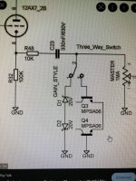
Is example with 2 different types of zener control from switch
Ok, but please do not call it gain.
Gain is NOT clipping or distortion, period, yet you use "the word" all the time.
This is a Tech based Forum, that word has a very definite meaning for all of us, and t´s confusing to say the least.
As of your video, it proves what added diodes do: turn strong muscular Tube distortion into fuzzy buzzy weeny SS distortion.
Listen to it yourself at 2:16 (ugh!, I almost puke) , go back and forth 20 times a few seconds before and after (say from 2:03 to 2:20.
He lost sound quality big time, (weak - thin - fuzzy) and LOST GAIN, so much so that he HAS to raise volume/gain by hand, by turning a potentiometer UP.
Flipping that switch turns a 100W tube Marshall driving 4 x 12" into a 15W SS practice amp with a wimpy 8" speaker ... at least soundwise.
Yes, I see the youtuber calls it "gain". ..... well, it is NOT.
One of the problems of "studying" at the "You Tube University" 😱
And notice he admits to cheating: "we had to normalize it up in post production".
In good English: "what I am showing you is not true".
Also at 3:52 to 4:15 "when clean you don´t notice much difference between one diode an the other"
Umm ... of course not. When NOT clipping why would they sound different?
I’m trying 2x 1N4148 like my draw and I hear some gain more but the volume drops and I hear noises and buzz
"Small volume drop and the tiniest amount of grit" ..... of course: "not clipping".
At 4:30 he again murders his sound.
Oh well, I can´t stand it any more.
Back to your problem:
Yup, that´s what happens, period.
What I have been saying from day 1.
And please do not use the word "gain" for that, even if youtuber does.
Not if you want help here, simply because we can´t communicate using different language.
I want to add more gain
I hear some gain more
the gain increase
I take more gain ?
why are you stick with the words ?
Gain is NOT clipping or distortion, period, yet you use "the word" all the time.
This is a Tech based Forum, that word has a very definite meaning for all of us, and t´s confusing to say the least.
As of your video, it proves what added diodes do: turn strong muscular Tube distortion into fuzzy buzzy weeny SS distortion.
Listen to it yourself at 2:16 (ugh!, I almost puke) , go back and forth 20 times a few seconds before and after (say from 2:03 to 2:20.
He lost sound quality big time, (weak - thin - fuzzy) and LOST GAIN, so much so that he HAS to raise volume/gain by hand, by turning a potentiometer UP.
Flipping that switch turns a 100W tube Marshall driving 4 x 12" into a 15W SS practice amp with a wimpy 8" speaker ... at least soundwise.
Yes, I see the youtuber calls it "gain". ..... well, it is NOT.
One of the problems of "studying" at the "You Tube University" 😱
And notice he admits to cheating: "we had to normalize it up in post production".
In good English: "what I am showing you is not true".
Also at 3:52 to 4:15 "when clean you don´t notice much difference between one diode an the other"
Umm ... of course not. When NOT clipping why would they sound different?
I’m trying 2x 1N4148 like my draw and I hear some gain more but the volume drops and I hear noises and buzz
"Small volume drop and the tiniest amount of grit" ..... of course: "not clipping".
At 4:30 he again murders his sound.
Oh well, I can´t stand it any more.
Back to your problem:
I’m trying 2x 1N4148 like my draw and I hear some gain more but the volume drops and I hear noises and buzz
Yup, that´s what happens, period.
What I have been saying from day 1.
And please do not use the word "gain" for that, even if youtuber does.
Not if you want help here, simply because we can´t communicate using different language.
Yea I understand for the word “gain” . otherwise it is in my mind and otherwise in its true sense… simply because he is a restless character .. I like to try things ,, and I would not say no to this type of switch. just to change the saturation a bit… so a few minutes ago I tried with 4x 1N4148 but the sound drops very and the distortions like a solid state amp . I don’t like this .. I’m keep to searching and testing …. Forgive me but when I get stuck with something, I want to get to the extremes….Thank you very much for your time and answer meOk, but please do not call it gain.
Gain is NOT clipping or distortion, period, yet you use "the word" all the time.
This is a Tech based Forum, that word has a very definite meaning for all of us, and t´s confusing to say the least.
As of your video, it proves what added diodes do: turn strong muscular Tube distortion into fuzzy buzzy weeny SS distortion.
Listen to it yourself at 2:16 (ugh!, I almost puke) , go back and forth 20 times a few seconds before and after (say from 2:03 to 2:20.
He lost sound quality big time, (weak - thin - fuzzy) and LOST GAIN, so much so that he HAS to raise volume/gain by hand, by turning a potentiometer UP.
Flipping that switch turns a 100W tube Marshall driving 4 x 12" into a 15W SS practice amp with a wimpy 8" speaker ... at least soundwise.
Yes, I see the youtuber calls it "gain". ..... well, it is NOT.
One of the problems of "studying" at the "You Tube University" 😱
And notice he admits to cheating: "we had to normalize it up in post production".
In good English: "what I am showing you is not true".
Also at 3:52 to 4:15 "when clean you don´t notice much difference between one diode an the other"
Umm ... of course not. When NOT clipping why would they sound different?
I’m trying 2x 1N4148 like my draw and I hear some gain more but the volume drops and I hear noises and buzz
"Small volume drop and the tiniest amount of grit" ..... of course: "not clipping".
At 4:30 he again murders his sound.
Oh well, I can´t stand it any more.
Back to your problem:
Yup, that´s what happens, period.
What I have been saying from day 1.
And please do not use the word "gain" for that, even if youtuber does.
Not if you want help here, simply because we can´t communicate using different language.
Couple of zener diodes from cathode follower's cathode to ground coupled capacitively should do the trick. (Yes, put them before the tonestack, not after it). May not be the ultimate distortion tone but back in the 1980's that was the thing of a very praised and famous amp modifier. Several amps still mimick the scheme.
And yes, it attenuates your signal volume because it's based on clipping peak amplitudes from the signal. When Randall did the same thing with their very famous RG80/100ES amps they ultimately had to add gain recovery stages to later versions to compensate the volume drop from toggling the "Extra Sustain".
And yes, it attenuates your signal volume because it's based on clipping peak amplitudes from the signal. When Randall did the same thing with their very famous RG80/100ES amps they ultimately had to add gain recovery stages to later versions to compensate the volume drop from toggling the "Extra Sustain".
Two 1N4148's in antiparallel will reduce the signal voltage to about 1.3 Vss. This is too low to drive the PI stage of your Marshall satisfyingly.
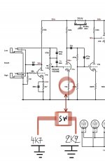
So new update … I use 2x 20volts zener ( -+ +- ) this I found on a forum ( 2009 post ) and the MIKE FORTIN answer to this post ..btw Mike fortin make the FORTIN AMPS at 2011 ,,, so I try this and I like the saturation of signal with little bit volume drop …and I make a second switch goes from cathode to the ground with 2 resistors . The first with 4k7 and the second with 2k2 for more gain ( now is gain 🙂 ) original schematic use 10k .
Attachments

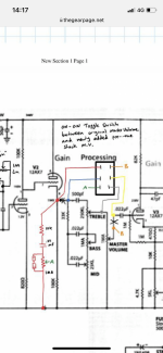
So can I put on cathode follower before the tone stack … parrallel with 100k from cathode ? Like this ? Right ?Couple of zener diodes from cathode follower's cathode to ground coupled capacitively should do the trick. (Yes, put them before the tonestack, not after it). May not be the ultimate distortion tone but back in the 1980's that was the thing of a very praised and famous amp modifier. Several amps still mimick the scheme.
And yes, it attenuates your signal volume because it's based on clipping peak amplitudes from the signal. When Randall did the same thing with their very famous RG80/100ES amps they ultimately had to add gain recovery stages to later versions to compensate the volume drop from toggling the "Extra Sustain".
Attachments
Yes, almost. The principle is correct and so is orientation of the zener diodes.
But the cathode is at about 180 volts of DC, which will saturate one of the diodes, so you also need a capacitor in series with those zener diodes to isolate them from that DC voltage potential. After that the Zeners effect only AC signals at the cathode and work properly.
Google search for "Jose mod".
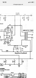
I found this one but I make it work without the switch that shows ,, I make with my way .. also I found and resonance pot on Jose mod … nice 👍Yes, almost. The principle is correct and so is orientation of the zener diodes.
But the cathode is at about 180 volts of DC, which will saturate one of the diodes, so you also need a capacitor in series with those zener diodes to isolate them from that DC voltage potential. After that the Zeners effect only AC signals at the cathode and work properly.
Google search for "Jose mod".
Attachments
That's one way to do it, also adding a bypass cap across the 10K resistor will bump the gain, and adjusting the 470K+470K voltage divider that proceeds the V1a stage.The first with 4k7 and the second with 2k2 for more gain ( now is gain 🙂 ) original schematic use 10k
What value of bypass cap ? 680NF… … I don’t understand the «adjusting the 470K+470K voltage divider that proceeds the V1a stage» ?That's one way to do it, also adding a bypass cap across the 10K resistor will bump the gain, and adjusting the 470K+470K voltage divider that proceeds the V1a stage.
Attachments
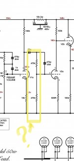
Actually you can check out Rob Robinette`s page for JCM800 mods, he explains the cold clipping stage (10K without bypass) and with your 4.7 K and 2.2K cathode resistors you can switch in the bypass capacitor. 680 nF might be a good place to start experimenting. That value will affect the low frequency rolloff of the added gain, so go smaller if bottom end too heavy, or bigger if it needs more bass. He also discusses the voltage divider.. CheersWhat value of bypass cap ? 680NF
https://robrobinette.com/How_the_Marshall_JCM800_Works.htm
What value of bypass cap ? 680NF… … I don’t understand the «adjusting the 470K+470K voltage divider that proceeds the V1a stage» ?That's one way to do it, also adding a bypass cap across the 10K resistor will bump the gain, and adjusting the 470K+470K voltage divider that proceeds the V1a stage.
- Home
- Live Sound
- Instruments and Amps
- Style JCM800 diode clipping