Actually those I got. They are the Zener replacements, correct? I understood that to be 3 LTL-4231N in series to replace the Zener. I'm looking for the single LED that you carry to the front panel as an indicator.
Yes, the ones I listed are for the LED mod for replacing the Zener diodes.
The indicator LED is coming from power supply PCB, right? Sorry, I used a different set of PCBs for my F6 clone build, and not 100% sure about the diyAudio store PCB.
The indicator LED is coming from power supply PCB, right? Sorry, I used a different set of PCBs for my F6 clone build, and not 100% sure about the diyAudio store PCB.
Last edited:
It actually comes off the amplifier board. The PSU has one as well. Im sure I would be able to calculate the voltage at a given point if I had a better idea what I was doing, however.......Im painting by the numbers right now.Yes, the ones I listed are for the LED mod for replacing the Zener diodes.
The indicator LED is coming from power supply PCB, right? Sorry, I used a different set of PCBs for my F6 clone build, and not 100% sure about the diyAudio store PCB.
If you are asking about the single LED (D1) on the schematic.
I believe it's any generic LED (as long as it's blue!) 😋
You adjust its brightness by altering R13 (15k nominal)
I believe it's any generic LED (as long as it's blue!) 😋
You adjust its brightness by altering R13 (15k nominal)
I'll go with that, maybe order a few different values and plan to fine tune. Appreciate it.If you are asking about the single LED (D1) on the schematic.
I believe it's any generic LED (as long as it's blue!) 😋
You adjust its brightness by altering R13 (15k nominal)
this is what I used for the F6 rail indicator LED: https://www.digikey.com/en/products...68022?s=N4IgTCBcDaIGwHYC0BGBAWAHEgcgERAF0BfIA


Pretty sure that's exactly what I ordered. Thanks muchthis is what I used for the F6 rail indicator LED: https://www.digikey.com/en/products...68022?s=N4IgTCBcDaIGwHYC0BGBAWAHEgcgERAF0BfIA
My F6 is complete and playing nicely. First impressions are that this is a bit cleaner sound than my ACAs. The ACA has that warm, seductive 2nd harmonic thing going that sounds so great and the F6 seems a bit more towards neutral. Perhaps less texture but more detail.
I tried to rig it to play with my powered subwoofers using an RCA splitter cable and promptly blew the fuse on the F6. Then I recalled something in NP's writing about how the grounds on this amp are special and won't play well with certain other types of equipment. Can anyone tell me what the right way to incorporate subs with this?
Also would it be possible to install balanced inputs on the F6? Has anyone done it and have a wiring diagram?
I don't know the answer regarding the cable splitter. However, the only way to run it balanced is to make it a monoblock. For two channels ran balanced, you would need four channel boards, two chassis and two power supplies.
There may be a workaround but I don't believe it'll actually be balanced.
There may be a workaround but I don't believe it'll actually be balanced.
Thanks Mike, another question I’d like to add to my list is whether these amps change as they “break in“. Do amps “break in” or is that a popular myth?I don't know the answer regarding the cable splitter. However, the only way to run it balanced is to make it a monoblock. For two channels ran balanced, you would need four channel boards, two chassis and two power supplies.
There may be a workaround but I don't believe it'll actually be balanced.
And let me take this opportunity to thank you and Dennis Hui and Zen Mod for all your help in getting this bird the fly. I could not have done it without you!
Bruce
No problem. Zen Mod and Dennis are very sharp. I always hear some of our more established members talk about letting the amps break in. They are also very quick to mention if something is useless so I believe that break in is a thing on amps. I feel that I heard a difference after about 50 hours or so.
I know it was a process but you got it working. Congratulations! The F6 is a wonderful design.
I know it was a process but you got it working. Congratulations! The F6 is a wonderful design.
I'd say " one more question " but that would suggest I'm almost done. So, another question. I seems soldering resistors so they touch the board isn't the best idea due to heat concerns. In the future I'll hold them off, but will these be an issue. And are any of the wild bends I have in these leads an issue. I would just rather correct now rather than compromise what I hope will be a great end product.
Attachments


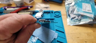
I don't think it will be a problem. I don't know of anyone having any issues with bending leads unless the outer coating cracks etc. Most resistors on the board will be close to ambient. The 3w resisters (source etc) get pretty warm but should still be okay. It is however good practice to elevate the larger resistors a little bit.
Also would it be possible to install balanced inputs on the F6? Has anyone done it and have a wiring diagram?
I'm in the process of attempting balanced F6s but, as Mikerodrig27 pointed out, they amount to two stereo amps with a balanced XLR input. In my F6 journey, I ran across mention of doing balanced via a single board but it amounted to circumventing the phase splitter function of the transformer (and possibly that F6 signature sound). As it required some surgery on the signal board, my cost function didn't tip me towards attempting it.
This weekend, I'm hoping to get the 2nd set of boards mounted in my monoblocks and see if the DC offset is low enough to use.
There are a few issues that have had me dragging my feet:
1.) running in balanced mode, the output impedance doubles.
2.) running in balanced mode, the distortion signature changes.
3.) doubled the heat. Great in winter. Not so great in summer.
I've been enjoying these F6s "single-ended" so much that I've not been wanting to take them back apart.
If issue #1 causes a woolier bass response, I have a quad of F5 boards ready to pop in and try.
If issue #2 sours the sound enough, I may just revert back to single-ended operation. Or try an F4 setup. With a tube-based gain stage...
I believe 6L6 has chimed in that he has not had "scorching" issues on the 3W resistors. I think the issue dates back to the old paper-based PCBs that didn't handle heat. I don't know what the coating was but I remember learning the hard way to raise the resistors as they would melt the coating and char the paper. I've not noticed any issues with, what I assume to be, glass-epoxy boards like diyAudio sells. Of course, mine have only been running for a few months now.I'd say " one more question " but that would suggest I'm almost done. So, another question. I seems soldering resistors so they touch the board isn't the best idea due to heat concerns. In the future I'll hold them off, but will these be an issue. And are any of the wild bends I have in these leads an issue. I would just rather correct now rather than compromise what I hope will be a great end product.
Last edited:
I finally completed the rebuild of my F6 today and I'm very glad I did that!
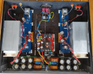
First off, replaced the cheap Chinese SMPS by a Connex SMPS300REh, then replaced the FQH44N10 mosfets with IRFP150. Also, I added a small card with extra caps directly at each of the F6 circuit boards. How much of a difference this makes is debatable, but I have the option to easily disconnect it for testing.
Replacing the mosfets was inspired by a test by @Mikerodrig27 (post #4035). I can only attest to his findings, the FQH44N10 has bass control to die for, if that's your thing, but fairly shallow mid and top end. IRFP150 has imaging, better soundstage and top end. The difference was very obvious when comparing with my ACA mini. It is still early (been running the F6 for two-three hours total). Now the F6 is on the path of putting the ACA mini where it belongs, in my study.
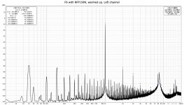
Objectively, using FQH44N10 gave slightly higher distortion levels and near equal 2nd and 3rd level harmonics, with IRFP150 the 2nd level is higher than the 3rd. The strange peak at about 8-9 kHz could be artifacts from the SMPS (just a guess from me). That peak was substantially higher with the old SMPS. Now the peak of the right channel is higher than the left, this correlates with higher levels of HF noise for the right channel (why?).
I will play with the power supply a bit more to see if it changes.
First off, replaced the cheap Chinese SMPS by a Connex SMPS300REh, then replaced the FQH44N10 mosfets with IRFP150. Also, I added a small card with extra caps directly at each of the F6 circuit boards. How much of a difference this makes is debatable, but I have the option to easily disconnect it for testing.
Replacing the mosfets was inspired by a test by @Mikerodrig27 (post #4035). I can only attest to his findings, the FQH44N10 has bass control to die for, if that's your thing, but fairly shallow mid and top end. IRFP150 has imaging, better soundstage and top end. The difference was very obvious when comparing with my ACA mini. It is still early (been running the F6 for two-three hours total). Now the F6 is on the path of putting the ACA mini where it belongs, in my study.
Objectively, using FQH44N10 gave slightly higher distortion levels and near equal 2nd and 3rd level harmonics, with IRFP150 the 2nd level is higher than the 3rd. The strange peak at about 8-9 kHz could be artifacts from the SMPS (just a guess from me). That peak was substantially higher with the old SMPS. Now the peak of the right channel is higher than the left, this correlates with higher levels of HF noise for the right channel (why?).
I will play with the power supply a bit more to see if it changes.
Attachments
Last edited:
I couldn't stand it and got some desoldering practice. Things like that can haunt me. Especially if it sounds great, which it will if I do my part, I'll be thinking just that slight misstep will shorten it's life. Was actually good practice and it didn't cost much.I'm in the process of attempting balanced F6s but, as Mikerodrig27 pointed out, they amount to two stereo amps with a balanced XLR input. In my F6 journey, I ran across mention of doing balanced via a single board but it amounted to circumventing the phase splitter function of the transformer (and possibly that F6 signature sound). As it required some surgery on the signal board, my cost function didn't tip me towards attempting it.
This weekend, I'm hoping to get the 2nd set of boards mounted in my monoblocks and see if the DC offset is low enough to use.
There are a few issues that have had me dragging my feet:
1.) running in balanced mode, the output impedance doubles.
2.) running in balanced mode, the distortion signature changes.
3.) doubled the heat. Great in winter. Not so great in summer.
I've been enjoying these F6s "single-ended" so much that I've not been wanting to take them back apart.
If issue #1 causes a woolier bass response, I have a quad of F5 boards ready to pop in and try.
If issue #2 sours the sound enough, I may just revert back to single-ended operation. Or try an F4 setup. With a tube-based gain stage...
I believe 6L6 has chimed in that he has not had "scorching" issues on the 3W resistors. I think the issue dates back to the old paper-based PCBs that didn't handle heat. I don't know what the coating was but I remember learning the hard way to raise the resistors as they would melt the coating and char the paper. I've not noticed any issues with, what I assume to be, glass-epoxy boards like diyAudio sells. Of course, mine have only been running for a few months now.
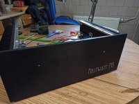
Finally completed my F6 build. This is my first FirstWatt DIY amp. A huge big thanks to Mr. Pass for sharing his design and the entire commumity here whose posts helped me and your builds inspired me. Thanks to @6L6 for the illustrated guides. I'm very glad I built this. The amp is super silent and sounded wonderful right away. Not sure if it gets better as it breaks in. Folks were not kidding when they said it gets hot. Right now it's peak of summer here with temps reaching 42C and I can barely touch the heatsinks for a sec!
The enclosure is DIY since importing the one from Modushop was getting very expensive. That turned out to be quite challenging it took the most time. It's aluminium and anodised.
Couple of questions
1. I've noticed that the bias voltage slowly keeps rising. When I set it at around 0.52V after 30 min of running I noticed that on cold start the bias is just about 0.47V and then slowly climbs up. Is this fine or should I set it so on cold start it is 0.5V and let it rise from there?
2. I've read that the offset won't remain steady at 0. It also seems to creep over time. What value is considered bad?
Sharing some pics..
Couple of questions
1. I've noticed that the bias voltage slowly keeps rising. When I set it at around 0.52V after 30 min of running I noticed that on cold start the bias is just about 0.47V and then slowly climbs up. Is this fine or should I set it so on cold start it is 0.5V and let it rise from there?
2. I've read that the offset won't remain steady at 0. It also seems to creep over time. What value is considered bad?
1, Bias alters as the amp warms up fully, it is somewhat temperature-dependent. So as long as it does settle, and not rise too high, all is fine.
2, As long as the offset is not hundreds of Mv, it's not a major problem. It should stabilize as above (eventually.)
- Home
- Amplifiers
- Pass Labs
- F6 Illustrated Build Guide