Hope to start building the Sissy this week. Can't wait to hear some SITs from a Mighty design >🙂
Hardest part will probably be forcing myself to take things nice and slow.
Any tips on drilling the rear panel for the panel mount fuse holders?
Since I'll be using the new Modushop mono chassis, would ZM & folks here recommend placing the donuts at the front of the chassis to try and minimize EMI (near rear panel I/O)?
Need to try for the best spot to mount fuse holders, then plan layout for power supply.
Oh, and the R.3 PCB doesn't share design with Babelfish, right? So I can mount components (diodes) per the silkscreen orientation?
Last edited:

I made the changes and all the connections check out but still no output.
On the transformer P3, is connected to ground and as I move from P2 (input) to P1, P7, P6, P5, (output) I see about a 40 ohm increases per step, just as I would expect.
I connect a signal, 1k, 1.5v and all is fine through the buffer out to P2, at P1 the signal is ~3v, same at P7, at P6 it is back to 1.5v and ~0 at P5 the output. It seems like the transformer is out of phase or something and I don't see an easy way to try to flip it.
I did briefly touch a wire from the buffer to R111, and got a squiggly line, (Technical term), so I think the output stage is working. I may try to lift R111 and connect to the buffer and try running it as an F4...John
will re-check things tonight, at latest
Hope to start building the Sissy this week. Can't wait to hear some SITs from a Mighty design >🙂
Hardest part will probably be forcing myself to take things nice and slow.
Any tips on drilling the rear panel for the panel mount fuse holders?
Since I'll be using the new Modushop mono chassis, would ZM & folks here recommend placing the donuts at the front of the chassis to try and minimize EMI (near rear panel I/O)?
Need to try for the best spot to mount fuse holders, then plan layout for power supply.
Oh, and the R.3 PCB doesn't share design with Babelfish, right? So I can mount components (diodes) per the silkscreen orientation?
see my latest posting in LuDEF thread for short photoshoot - how I'm orienting parts in more or less best way
regarding orientation parts - with R.3 everything goes as printed on pcb, no worries there
Back onto my SissySIT build today, installed the speaker terminals, input sockets and a switched shunt attenuator on the front end.
Rechecked all the bias and offset and had a listen using some old the Mission speakers. Not an ideal test arrangement, my smartphone didn't have enough gain so I ended up using my Noir HPA as a preamp, and the Missions haven't been used for a long time, so the music was a bit compromised. After 30-40mins the SissySIT was just starting to warm up (literally) and the speakers were starting to relax a bit so the sound was improving and there were clues to this being a really good amplifier.
The build is all but finished now, all that's left to do are front and rear panels for the chassis.

That's a short photoshoot? I spent a while scrolling through pics, thanks for the info.see my latest posting in LuDEF thread for short photoshoot - how I'm orienting parts in more or less best way
regarding orientation parts - with R.3 everything goes as printed on pcb, no worries there
Seems I need to figure out how to mount my transformers vertically.
Randy
fancy Z-Foil hanging ones .......
They're sleeping, wake up at dusk!
The toroid in my SissySIT lives in a 4 sided steel cage built of 3 panels of the perforated steel panel from the DIYAudio store, bolted to the inside bottom panel. The switch circuit is mounted on top of that. Be sure to not let the bolt, holding the toroid, touch the top of the cage. I have no hum, despite 95db speakers.
SissySIT R3 is truly wonderful sounding. You will love yours.
SissySIT R3 is truly wonderful sounding. You will love yours.
That was a very enjoyable hour! I hooked the SissySIT up to my Lowthers, source was my build of Marcel's ValveDAC DSD decoder, straight into the SissySIT, and I played a variety of tracks at DSD256 via HQPlayer.
There was a little edginess at the top end to start but that was definitely reducing as the SissySIT warmed up and got into it's stride. Detail and separation are excellent and the bass seems to have more 'oomph' about it than I have experienced with any other amp driving the Lowthers - reminded me of my 300B SE-OTL amps but after they had been on a diet of steroids! I have a tiny bit of buzz/hum if I put my ears close to the drive units but I have to say I didn't pay much attention to the cabling when i set it up and I'll check it out later - it didn't stop me from smiling as I tried different tracks. With a few more hours clocked up this is going to be an excellent amplifier, it's really very good straight off the building blocks.
It will be interesting to see how it compares to 1Watt from the 6C33C SE-OTL I'm slowly putting together.
Last edited:
Mocking Mode On:
-now's time to obtain better speakers than those
well, I'm really never outa Mocking Mode
now, on more serious note - you ought to try anything giving foundation based on at least 12" or even better - 15"
only then those A Class Watts (whichever amount is in case) are fully engaged
I'm still Greatest World's Full Range Fan, but that passion prevailed with passion for 15" coaxes
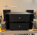
Introducing some Big Sissys.
In this corner weighing in at 80 lbs.
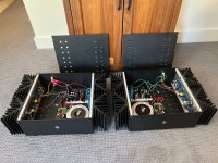
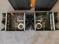
Finally completed my Sissysit. Had been contemplating this project since the first version of the boards. Waited until R.3 to complete as it seemed like a more simple and reliable way to ensure that my SITs were within the acceptable range. Although Pras had measured and they seemed fine. I double checked and the were
Big thanks to ZM and Nelson for making this all possible. I have been following along on this forum for nearly 18 year now. For this project picked Chassis that I had built 15 years ago. Heat sinks salvaged from someone’s Zen project gone wrong. Had them cut and made in to two chassis. Altogether each amp weighs 40lb. As they are each mono could remove heat sinks on one side and likely make another pair of monoblocks although I have no desire to tap heat sinks ever again. Didn’t want to try and fit two, two cap banks and two soft start modules in one chassis and power supplies as dislike working in that tight of space and concerned about hum. I located the transformer as far as possible from the cinemags. No hum to my ear on test speakers.
Also decided to use Mark Johnsons soft start as wanted to be able to turn the amp on from the front. As I disliked playing twister any time I wanted to listen to music. Works very well. Thanks!.
I was lured by the thought of miniscule power supply ripple and used “SLB” Smooth like butter cap mult. Was planning on about 5 V of dropout and picked the antec 4222. So one transformer and one SLB per chassis.
To my surprise everything worked first time in regards to power supply and soft start. Ended up with 31.4V unloaded from the SLB. When attached to sissysit boards came down to 29.2 V and when attached to speaker and playing music came down to 28.8 V. Seems a bit high for a firstwatt type amp. Had anticipated about 4-5V drop. My line voltage is 124-125V AC
Do you think that this will present any problems?
ZM Mentions concern about the IRFP down (I assume this is the 9140?) power dissipation being 45-50W. I’m not sure which way is up or down most of the time so excuse my confusion. Post 624, “sole thing to take care of his dissipation of puny IRFP down (45 to 50 W with exquisite cooling arrangement)”
Although I am certainly confused by the data sheet Power Dissipation (Max)=180W .
The IRF510 Has Power Dissipation max of 43 W. Anyway I really didn’t want to break the parts. So am I correct that power dissipated by each part Sit and mosfet is P=IE or 1.8Ax 28.8V=51.84W? or roughly 100W per side? Given my higher power supply rails.
The build went well and double checked parts with my trusty DMM. Powered up with Variac and proceeded to adjust as per mighty ZM’s instructions.
The amp power up went well. Able to follow clear instructions and able to figure out what way to turn the pots. Able to get the bias up to 160mV across the sensing resistor, set DC offset with input shorted, then set the buffer to 20mV and 0 offset and replace the jumper. Then on to 198mV for 1.8A. Able to set the DC offset with inputs shorted. Bias remained stable through out the testing.
DC Offset Drift with Temperature.
The curious part/ problem is that the DC offset slowly stabilizes and appears temp dependent.
Offset will tend to do the following. Inputs shorted.
Left channel
Initially 2 min in =-44mV, 30 min=+29mV, 90 min =+77mV, 180min=+90mV, 280min=96.9 mV, 480 min=97mV. If I remove the chassis top there will be decline in offset by 40=50 mV. If I should gently blow on board can drive the offset down by 100mV.
Right Channel
Initial 2 min=-57mV, 30 min=+41mV, 90min=+56mV, 180min=+68mV, 280min=+68mV, 480min=+72mV
Again when chassis top removed immediately steady decline in offset and if gentle blow on board will go down up to 100mV.
When tops placed back on will be steady rise back to the point where they were thermally stable.
Temp of the mega chassis is only 115F -46 C “Blimey Hot” after 3 hours. Appears to be thermally stable after about 4 hours. Could keep hand on sink indef. Infrared gun on Tokin and on board also don’t register very warm. Thermocouple for Fluke confirmed temp less about 45C. Appear to have good coupling to heat sinks.
Followed your comments about Chede’s issues with offset. Hoped to not undertake a lot of part replacement so decided to measure most everything to try and see how to proceed if necessary.
Used stock parts from kit with exception of some PRP 100R resistors. Level Shifters are 120R
Left Channel measurements after reaching thermal stability
SIT Vgs=-3.446V Voltage drop across gate resistor R226=0.0 V
IRFP9140 Vgs=4.068 Voltage drop across gate Resistor R225=1.9mV
IRF 510 Vgs=3.386
Bias Voltage across R0R22 resistor =198mV
Voltage drop across Level Shifter R215 = 3.27V
Right Channel measurements
SIT Vgs=-3.533V Voltage drop across gate resistor=0.6mV
IRFP9140 Vgs=4.086V Voltage drop across gate resistor = 0.0 mV
IRF510 Vgs=3.515V
Bias voltage across R022 resistor =197mV
Voltage across level shifter R115=3.534V
So the good news is that it works. Sounds quite nice on some ancient bookshelf speakers with iPhone as source. I realize that I can tolerate some DC offset but seems something is a bit touchy. Hopefully something can be done to tame this offset issue. Once I can verify that these are well behaved Big Sissys would like to have them play with my Harbeths and give my F5 a breather.
And for reading all this I present some pics. Many thanks to ZM for the endless support and answering the same questions over and over and over. If he could only answer why I can't remember the answers or why I forget to use the search function....... Also big thanks to Nelson for leading the way. I wouldn't have been down this path without them and the encouragement of all on this forum!
Jack
In this corner weighing in at 80 lbs.
Finally completed my Sissysit. Had been contemplating this project since the first version of the boards. Waited until R.3 to complete as it seemed like a more simple and reliable way to ensure that my SITs were within the acceptable range. Although Pras had measured and they seemed fine. I double checked and the were
Big thanks to ZM and Nelson for making this all possible. I have been following along on this forum for nearly 18 year now. For this project picked Chassis that I had built 15 years ago. Heat sinks salvaged from someone’s Zen project gone wrong. Had them cut and made in to two chassis. Altogether each amp weighs 40lb. As they are each mono could remove heat sinks on one side and likely make another pair of monoblocks although I have no desire to tap heat sinks ever again. Didn’t want to try and fit two, two cap banks and two soft start modules in one chassis and power supplies as dislike working in that tight of space and concerned about hum. I located the transformer as far as possible from the cinemags. No hum to my ear on test speakers.
Also decided to use Mark Johnsons soft start as wanted to be able to turn the amp on from the front. As I disliked playing twister any time I wanted to listen to music. Works very well. Thanks!.
I was lured by the thought of miniscule power supply ripple and used “SLB” Smooth like butter cap mult. Was planning on about 5 V of dropout and picked the antec 4222. So one transformer and one SLB per chassis.
To my surprise everything worked first time in regards to power supply and soft start. Ended up with 31.4V unloaded from the SLB. When attached to sissysit boards came down to 29.2 V and when attached to speaker and playing music came down to 28.8 V. Seems a bit high for a firstwatt type amp. Had anticipated about 4-5V drop. My line voltage is 124-125V AC
Do you think that this will present any problems?
ZM Mentions concern about the IRFP down (I assume this is the 9140?) power dissipation being 45-50W. I’m not sure which way is up or down most of the time so excuse my confusion. Post 624, “sole thing to take care of his dissipation of puny IRFP down (45 to 50 W with exquisite cooling arrangement)”
Although I am certainly confused by the data sheet Power Dissipation (Max)=180W .
The IRF510 Has Power Dissipation max of 43 W. Anyway I really didn’t want to break the parts. So am I correct that power dissipated by each part Sit and mosfet is P=IE or 1.8Ax 28.8V=51.84W? or roughly 100W per side? Given my higher power supply rails.
The build went well and double checked parts with my trusty DMM. Powered up with Variac and proceeded to adjust as per mighty ZM’s instructions.
The amp power up went well. Able to follow clear instructions and able to figure out what way to turn the pots. Able to get the bias up to 160mV across the sensing resistor, set DC offset with input shorted, then set the buffer to 20mV and 0 offset and replace the jumper. Then on to 198mV for 1.8A. Able to set the DC offset with inputs shorted. Bias remained stable through out the testing.
DC Offset Drift with Temperature.
The curious part/ problem is that the DC offset slowly stabilizes and appears temp dependent.
Offset will tend to do the following. Inputs shorted.
Left channel
Initially 2 min in =-44mV, 30 min=+29mV, 90 min =+77mV, 180min=+90mV, 280min=96.9 mV, 480 min=97mV. If I remove the chassis top there will be decline in offset by 40=50 mV. If I should gently blow on board can drive the offset down by 100mV.
Right Channel
Initial 2 min=-57mV, 30 min=+41mV, 90min=+56mV, 180min=+68mV, 280min=+68mV, 480min=+72mV
Again when chassis top removed immediately steady decline in offset and if gentle blow on board will go down up to 100mV.
When tops placed back on will be steady rise back to the point where they were thermally stable.
Temp of the mega chassis is only 115F -46 C “Blimey Hot” after 3 hours. Appears to be thermally stable after about 4 hours. Could keep hand on sink indef. Infrared gun on Tokin and on board also don’t register very warm. Thermocouple for Fluke confirmed temp less about 45C. Appear to have good coupling to heat sinks.
Followed your comments about Chede’s issues with offset. Hoped to not undertake a lot of part replacement so decided to measure most everything to try and see how to proceed if necessary.
Used stock parts from kit with exception of some PRP 100R resistors. Level Shifters are 120R
Left Channel measurements after reaching thermal stability
SIT Vgs=-3.446V Voltage drop across gate resistor R226=0.0 V
IRFP9140 Vgs=4.068 Voltage drop across gate Resistor R225=1.9mV
IRF 510 Vgs=3.386
Bias Voltage across R0R22 resistor =198mV
Voltage drop across Level Shifter R215 = 3.27V
Right Channel measurements
SIT Vgs=-3.533V Voltage drop across gate resistor=0.6mV
IRFP9140 Vgs=4.086V Voltage drop across gate resistor = 0.0 mV
IRF510 Vgs=3.515V
Bias voltage across R022 resistor =197mV
Voltage across level shifter R115=3.534V
So the good news is that it works. Sounds quite nice on some ancient bookshelf speakers with iPhone as source. I realize that I can tolerate some DC offset but seems something is a bit touchy. Hopefully something can be done to tame this offset issue. Once I can verify that these are well behaved Big Sissys would like to have them play with my Harbeths and give my F5 a breather.
And for reading all this I present some pics. Many thanks to ZM for the endless support and answering the same questions over and over and over. If he could only answer why I can't remember the answers or why I forget to use the search function....... Also big thanks to Nelson for leading the way. I wouldn't have been down this path without them and the encouragement of all on this forum!
Jack
Attachments
simply great!
now, two things:
- you have proper calc for OS parts dissipation ( no worries about TO220 IRF) ; if there is Keratherm 86/82 thermal pad, no worries
- output DC offset - set it to 0mV in temp equilibrium, and just chill
if you want it even more stable , there is tweak for ya, fine tuning value of level shifter resistor; as already explained somewhere with my crude sketches (post #2 and more, this thread), devil is in closest possible same value of resistors going from rails to mosfet gates
now; channel one ;
3V27 across 120R means roughly 28mA Iq of level shifter Source follower ( IRF510)
now, present difference of Ugs between upper and lower mosfet is 4.068V-3.386V=0V682
which means - for equilibrium of upper and lover Ugs we need to compensate Level shifter resistor value for that voltage drop
so, R=U/I=0V682/28mA= 24R
conclusion - increase value of R215 for 24R, so just use first standard value - 150R
same logic applies for other channel :
3V534 across 120R means roughly 30mA Iq of level shifter Source follower ( IRF510)
now, present difference of Ugs between upper and lower mosfet is 4.086V-3.515V=0V571
which means - for equilibrium of upper and lover Ugs we need to compensate Level shifter resistor value for that voltage drop
so, R=U/I=0V571/30mA= 19R
conclusion - increase value of R115 for 19R, so just use first standard value - 150R
all that just to explain how to guild the lily, not because DC offset is critical - it is damn good already taking in account that setting output node level is strictly passive - with resistive voltage divider, no even slightest servo function around
I'm good even with 500mV (or even higher) of initial DC Offset, under condition that there are no abrupt changes (thump) and that Offset is stable in temp. equilibrium
just informative - same OS governed with active FE, as in SissySIT P - stays within 5mV from damn cold to damn hot, with rails variation (Variac) of 40-50%
and yes - it's good that you have opportunity to use plain new sides instead of those redundant heatsinks, so you can make another pair of monoblock cases 🙂
edit: clarification of power dissipation of IRFP parts - download datasheet and read them and stare at graphs; these parts are switching thingies, and ppl making them are declaring most numbers with that function as main context
so, simply put - they can endure much higher currents for short duration ( impulses) than they can in steady condition; main problem not being current capability but ability of relatively small physical mosfet case to conduct all that heat fast enough
so - put IRFP on small heatsink , it'll die very soon with just 20W of heat
use longer wires and toss that same mosfet with same small heatsink in bucket of oil ( HAM trick from Yore, having toob bottle in bucket of oil) , it'll endure 100W of dissipation for years
go figure
now, two things:
- you have proper calc for OS parts dissipation ( no worries about TO220 IRF) ; if there is Keratherm 86/82 thermal pad, no worries
- output DC offset - set it to 0mV in temp equilibrium, and just chill
if you want it even more stable , there is tweak for ya, fine tuning value of level shifter resistor; as already explained somewhere with my crude sketches (post #2 and more, this thread), devil is in closest possible same value of resistors going from rails to mosfet gates
now; channel one ;
Left Channel measurements after reaching thermal stability
....
IRFP9140 Vgs=4.068 Voltage drop across gate Resistor R225=1.9mV
IRF 510 Vgs=3.386
Bias Voltage across R0R22 resistor =198mV
Voltage drop across Level Shifter R215 = 3.27V
3V27 across 120R means roughly 28mA Iq of level shifter Source follower ( IRF510)
now, present difference of Ugs between upper and lower mosfet is 4.068V-3.386V=0V682
which means - for equilibrium of upper and lover Ugs we need to compensate Level shifter resistor value for that voltage drop
so, R=U/I=0V682/28mA= 24R
conclusion - increase value of R215 for 24R, so just use first standard value - 150R
same logic applies for other channel :
Right Channel measurements
....
IRFP9140 Vgs=4.086V Voltage drop across gate resistor = 0.0 mV
IRF510 Vgs=3.515V
Bias voltage across R022 resistor =197mV
Voltage across level shifter R115=3.534V
3V534 across 120R means roughly 30mA Iq of level shifter Source follower ( IRF510)
now, present difference of Ugs between upper and lower mosfet is 4.086V-3.515V=0V571
which means - for equilibrium of upper and lover Ugs we need to compensate Level shifter resistor value for that voltage drop
so, R=U/I=0V571/30mA= 19R
conclusion - increase value of R115 for 19R, so just use first standard value - 150R
all that just to explain how to guild the lily, not because DC offset is critical - it is damn good already taking in account that setting output node level is strictly passive - with resistive voltage divider, no even slightest servo function around
I'm good even with 500mV (or even higher) of initial DC Offset, under condition that there are no abrupt changes (thump) and that Offset is stable in temp. equilibrium
just informative - same OS governed with active FE, as in SissySIT P - stays within 5mV from damn cold to damn hot, with rails variation (Variac) of 40-50%
and yes - it's good that you have opportunity to use plain new sides instead of those redundant heatsinks, so you can make another pair of monoblock cases 🙂
edit: clarification of power dissipation of IRFP parts - download datasheet and read them and stare at graphs; these parts are switching thingies, and ppl making them are declaring most numbers with that function as main context
so, simply put - they can endure much higher currents for short duration ( impulses) than they can in steady condition; main problem not being current capability but ability of relatively small physical mosfet case to conduct all that heat fast enough
so - put IRFP on small heatsink , it'll die very soon with just 20W of heat
use longer wires and toss that same mosfet with same small heatsink in bucket of oil ( HAM trick from Yore, having toob bottle in bucket of oil) , it'll endure 100W of dissipation for years
go figure
Last edited:
ZM,
Thank your instantaneous reply. I really appreciate your walking me through the logic of "guilding the lily". Part of what got me into this hobby is trying to understand the why and how these circuits work. Now that I am retired I have enough time and "bandwidth" to read and reread and more importantly actually build and measure. I've read the level shifter and optocoupler parts of this thread many times and still find it a bit of magic trick.
Will try and get these beasts up the thermal equilib (4 hours) and then set offset then wait to see if it will drift into +/- 20 mV (likely 20 min after reset with top back on).
Curious at to what part is so temp sensitive? Trim pot, Gate resistor, level shifter. optocoupler?
Will likely spare myself lily guilding for now. Might just have to wait to have a Sissysit P or some other flavor of the month. Have parts for the M2X and a 400U chassis and will likely complete that next.
I like the symmetry of the amps with both heat sinks, but they are too wide for a standard rack. total width 22". right now the look a little "steam punk". Will most likely remove the extra sink as one can never have too many chassis. Also need to figure out design and lettering for front so proper homage can be paid to the mighty ZM . Maybe will use the stores service. Was too lazy to figure out Front Panel Express software.
and also thanks for the explanation about power dissipation. With the amount of aluminum used here and adequate keratherm the SIT, and mosfet seem to be pretty well "oiled".
Will post review of "sound" once the rest of this put to bed.
And one more thing. I think that you ought to have a Thread/Sticky of pictures of builds your designs. They are sort of spread all over. Not sure if we should post to the "diy Pass Amplifier" thread. Although many amplifiers are derivative, Pics of Iron Pumpkin and or turtle should have there own home. Just sayin....
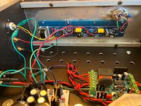
Looking at how things might be laid out (at a single channel... donuts and PSU will be stacked).
I'm thinking of tapping holes for SIT in this general vicinity -- probably slightly more towards the center of the heatsink/chassis (a bit further away from donuts).


I'm thinking of tapping holes for SIT in this general vicinity -- probably slightly more towards the center of the heatsink/chassis (a bit further away from donuts).
- Home
- Amplifiers
- Pass Labs
- SissySIT R.3