No. I checked a few times. And I just soldered the 82R in.
Bad SIT, or something wrong on the way to the SIT?
I was measuring incorrectly for the -1R7, I had incorrect info about the SIT pins. Now measuring big vs small leg, not bolt/case.
Bad SIT, or something wrong on the way to the SIT?
I was measuring incorrectly for the -1R7, I had incorrect info about the SIT pins. Now measuring big vs small leg, not bolt/case.
you're confusing me
thin pin of SIT is Gate, fat pin is Source, Body is Drain
red probe on Gate (thin pin), Black probe on Source (fat pin)
anyway, those Ugs voltages are informative, whats important of course is to set amp's Iq and DC Offset on output
as far as I understood , you did that successfully
now, I need those Ugs voltages mostly as additional info
Those measurements in post #740 are done correctly, according to your statement above
yes, and Bias and offset are correct in both channels 198mv, and 0 offset.
yes, and Bias and offset are correct in both channels 198mv, and 0 offset.
so , just confirm that is properly written as this ( I edited your typo of 22.3V, for Side B):
if that is correct, you're more than good
as I said - for signal , value of R115 is irrelevant
Side A SIT -2.89 Big Mosfet -4.16 Small 3.58 (R115 = 120R)
Side B SIT -2.23 Big Mosfet -4.2. Small 3.58 (R115 = 82R)
if that is correct, you're more than good
as I said - for signal , value of R115 is irrelevant
amp is functional, you have both Iq ( around 1A8) and output offset (as close to 0V), as you want?
I have not hooked up speakers, but Bias and offset are fine on both channels.
once I changed R115 to 82R, bias and offset were easily set, finalized at 2 hours.
once I changed R115 to 82R, bias and offset were easily set, finalized at 2 hours.


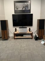
The Beast is singing, and sweetly. I dragged her upstairs to the man cave and started with the computer monitor speakers as test. (lower sensitivity, and $) They played well together enough to hook up the mains.
1) seems like a bit less gain than M2x, so pre was up a few clicks.
2) a bit more organic, and textured sound compared to M2x
3) no channel imbalance, despite the issues with that one channel
4) great imaging, although not as good as the monoblock M2x, so not fair
5) temps 44c on black heatsink adjacent to the SIT. similar both sides
More testing this weekend, preferably when wife and son go out for coffee. I already had loudness complaints today, despite slightly more than moderate levels.
I also want test direct XLR input, I currently use longish XLR cables to Jensen transformer box converting to short RCA cables which I use for most my amps.
Thanks so much ZM, this is a nice amp. Great design, and thanks for helping me getting it running right.
Attachments
Last edited:
1. dunno for M2x ( lazy to check) but if there is Edcor 600:15K involved , that's the reason - Sissy using classic repeaters (600ct:600ct), resulting in slightly lesser gain ; 600:15K giving 6V/V, while repeaters giving 4V/V
2. give it time, it'll bloom even more; M2 is best amp around, but SissySIT isprobably certainly best M2 around 
3. I've told you that value of Level Shifter Resistor is having nothing with AC Domain/Signal/Music
4. Monoblocks are proper way for maximized channel separation; common PSU for both channels is always erring on organicity side, while reducing levels of tiny details ...... so , matter of taste - some people are preferring common PSU, some Mono PSU; I prefer Mono PSU
2. give it time, it'll bloom even more; M2 is best amp around, but SissySIT is
3. I've told you that value of Level Shifter Resistor is having nothing with AC Domain/Signal/Music
4. Monoblocks are proper way for maximized channel separation; common PSU for both channels is always erring on organicity side, while reducing levels of tiny details ...... so , matter of taste - some people are preferring common PSU, some Mono PSU; I prefer Mono PSU
I think it gets better with some run-in time as ZM mentions. And I usually don't sit down and listen these days until my amps are warmed up for 30 to 45 minutes at least.
I'm not that picky...... enjoying it from dead cold to powering Off
simple - while amp is cold, just use some hotter music

basically - when you have a good amp, it is good enough from cold
simple - while amp is cold, just use some hotter music
basically - when you have a good amp, it is good enough from cold
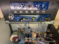
I know I am late to the party but I finely got the kit together and in the case. It fired up up perfectly the first time, it just took a looong time for the current to start to come up but once it did everything is right in. I am a bit leery about the blue silicone pads I used to mount the SIT. They are awful squishy and I was afraid to compress it too much, might look for something better. But as it sits with the current up to about 180ma the temp at the case is about 72c. I am a tube guy so I am not sure how hot is too hot.
It is in a U5 case, plenty of room for 2 amps and as you can see we may soon know the answer to the burning question, can it drive an F4?...John
It is in a U5 case, plenty of room for 2 amps and as you can see we may soon know the answer to the burning question, can it drive an F4?...John
Attachments
if it's 72C on SIT case, then you really need to find some other thing to put as isolator
it'll endure that, but it's really pity to torture it that way
Conrad.de is having Keratherm 86/82 sheets, Boyz did found some special made Alumina oxide pads, and there must be (somewhere) mica sheets
heck, even gray squishy pads are better than that bluish thing
it'll endure that, but it's really pity to torture it that way
Conrad.de is having Keratherm 86/82 sheets, Boyz did found some special made Alumina oxide pads, and there must be (somewhere) mica sheets
heck, even gray squishy pads are better than that bluish thing
I finely got some better insulators for the SIT and now my temp is about 47c, a very dramatic improvement. I will not waste my time with the blue stuff again.
On to the next issue, I am not getting any signal out. I have traced it through the buffer OK and seem to be losing it through the transformer. I am using the Edcor 600/600 and I am sure it is fitted correctly. It is the same on both channels, so it's not a bad transformer or solder joint. I can only reach the top row of connections of the transformer unless I take the case apart and before I do that I thought I would ask it see if I am missing something stupid. I do see signal at the top pins, I am guessing P1 and P2, hard to see. and the jumper is connected But nothing at R111...John
On to the next issue, I am not getting any signal out. I have traced it through the buffer OK and seem to be losing it through the transformer. I am using the Edcor 600/600 and I am sure it is fitted correctly. It is the same on both channels, so it's not a bad transformer or solder joint. I can only reach the top row of connections of the transformer unless I take the case apart and before I do that I thought I would ask it see if I am missing something stupid. I do see signal at the top pins, I am guessing P1 and P2, hard to see. and the jumper is connected But nothing at R111...John
Last edited:
well, in case of Edcor, someone was stupid, but certainly not you
check very bottom of Post #1 here : https://www.diyaudio.com/community/...-building-tips-and-tricks.329316/post-5586785
check very bottom of Post #1 here : https://www.diyaudio.com/community/...-building-tips-and-tricks.329316/post-5586785
Ok so cut the trace and jump, looks like 2J to jumper pin2. I will have to pull the boards and get back to you. I am using the S3 boardswell, in case of Edcor, someone was stupid, but certainly not you
check very bottom of Post #1 here : https://www.diyaudio.com/community/...-building-tips-and-tricks.329316/post-5586785
Looking at the schematic it looks like I should be able to remove the jumper and connect the Edcor pin 2 to the jumper pin 1?
as test, yes
for good, best to do as described, so youstill have jumper functionality, if needed
for good, best to do as described, so youstill have jumper functionality, if needed
I made the changes and all the connections check out but still no output.
On the transformer P3, is connected to ground and as I move from P2 (input) to P1, P7, P6, P5, (output) I see about a 40 ohm increases per step, just as I would expect.
I connect a signal, 1k, 1.5v and all is fine through the buffer out to P2, at P1 the signal is ~3v, same at P7, at P6 it is back to 1.5v and ~0 at P5 the output. It seems like the transformer is out of phase or something and I don't see an easy way to try to flip it.
I did briefly touch a wire from the buffer to R111, and got a squiggly line, (Technical term), so I think the output stage is working. I may try to lift R111 and connect to the buffer and try running it as an F4...John
- Home
- Amplifiers
- Pass Labs
- SissySIT R.3