Not my idea, is from Dynavox. Even worse with the Radford ECC81, only -0,4V.In view of grid current, 0,5 V is too low for my taste.
By lowering the 470k screen resistance you need more negative voltage to get the same anode current.
Mona
Forget this comment. You ARE building a nice amp. Much better then dynavox !Why do you say this?
Now I have all the components and I would like to take away the whim of hearing him play.
To recapitulate:
-disconnect NFB in case it's oscillating
-remove the couplings caps to the EL34 just to make sure it will power up
with no problems. Then adjust bias and see if it stays on. power off
- reconnect coupling caps ( at least one of them, remove the ECF82 tube and
power up. If successfull there is something fishy with the ecf82 neighborhood.

Not your idea, but you did suggest it.Not my idea, is from Dynavox. Even worse with the Radford ECC81, only -0,4V.
By lowering the 470k screen resistance you need more negative voltage to get the same anode current.
Mona
I don't know how you reached -0.4 V for the ECC81 in the amplifier of TS. When looking at the curves I think it will be around -0.7 V for the lower triode.
I think that when I wrote my post #2, the schematic that is now attached to post #1 didn't show 1K as the value of cathode resistor of the upper triode yet. I assumed it would be something like 510, so almost the same as the cathode resistors of the lower triode.
sorry, I did a ******** with the first post!
between the wrong links and the translation I have generated confusion.
so no fights please, if you really want to hit someone I'm the culprit. 🙂🙂🙂🙂😛😛😛
between the wrong links and the translation I have generated confusion.
so no fights please, if you really want to hit someone I'm the culprit. 🙂🙂🙂🙂😛😛😛
ok,Forget this comment. You ARE building a nice amp. Much better then dynavox !
To recapitulate:
-disconnect NFB in case it's oscillating
-remove the couplings caps to the EL34 just to make sure it will power up
with no problems. Then adjust bias and see if it stays on. power off
- reconnect coupling caps ( at least one of them, remove the ECF82 tube and
power up. If successfull there is something fishy with the ecf82 neighborhood.
Tonight I check the relay first (after the previous comments I have a terrible doubt) and then I do the tests you suggested.
Thanks again to everyone for the support and advice
With different resistors at the cathodes the voltage between the triodes is not halfway no more. With only 30V left for the bottom one you get only -0,4...-0,5V on the grid to get some current flowing.Not your idea, but you did suggest it.
I don't know how you reached -0.4 V for the ECC81 in the amplifier of TS. When looking at the curves I think it will be around -0.7 V for the lower triode.
I think that when I wrote my post #2, the schematic that is now attached to post #1 didn't show 1K as the value of cathode resistor of the upper triode yet. I assumed it would be something like 510, so almost the same as the cathode resistors of the lower triode.
With 30V on the grids of the inverter there is quite a DC unbalance at the anodes. 40V, as with equal cathode resistors, looks better.
And the common cathode resistor of only 2k2 gives an AC difference at the anodes in the order of 5(pentode) to 4(triode)
Mona
Attachments
unfortunately last night I was not well (and even today I'm not well) and I was not able to do all the tests.Forget this comment. You ARE building a nice amp. Much better then dynavox !
To recapitulate:
-disconnect NFB in case it's oscillating
-remove the couplings caps to the EL34 just to make sure it will power up
with no problems. Then adjust bias and see if it stays on. power off
- reconnect coupling caps ( at least one of them, remove the ECF82 tube and
power up. If successfull there is something fishy with the ecf82 neighborhood.
I checked the relay and everything seems fine.
I tried to do a ignition without the NFB connected and without the ECC81 and PCF82 tubes, so with only the EL34s mounted, in this case the fuse did not blow.
I tried to detect the voltages "under load" and these are the differences:
- BIAS no-load -59V
- Bias under load -57V
- B + no-load 465V
- B + under load 435 / 440V
after a few minutes I tried to calibrate the bias and the first oddity appears, as despite having both tubes the same negative voltage on the testpoints I find completely different values as shown in the following image..
also V1 had a glow inside (see photo) while V2 had nothing (only the heater light)
after a few minutes in this situation the fuse has tripped.
when I am better I will try to do the various tests including that of desoldering the coupling capacitors.
Oltre al post precedente, invio le foto dei due tubi.
V1 with inner glow

V2 without internal glow

V1 with inner glow
V2 without internal glow
Based on your measurements, the EL34 (V2 in your schematic in post #27) draws 94.6 mA, rising to 96.6 mA, which at 435 V would give a dissipation of 42 Watt, so far over the limit.
The other EL34 (V1) starts of at only 2.3 mA, which I think is OK.
If there are no wiring mistakes, your measurements point to a faulty V2. Or the coupling capacitor to the control grid of V2 is leaking (like petertub already pointed out).
What I don't understand is why V1 has inner glow, while in V2 you only see the heater. I would expect it the other way around.
Last edited:
The tube V1 is the one that glows inside ? It should be discarded. In fact
you should get a matched pair of new EL34 .
Adjustment of bias should be done to have equal current. Ignore grid voltage !
The voltage across an 1 ohm resistor should be at most 50mV ! 40-45 is good enough.
It is easier to use 10 ohm resistor then the voltage is easier to measure.!
you should get a matched pair of new EL34 .
Adjustment of bias should be done to have equal current. Ignore grid voltage !
The voltage across an 1 ohm resistor should be at most 50mV ! 40-45 is good enough.
It is easier to use 10 ohm resistor then the voltage is easier to measure.!
Tonight I did some tests after I left the hospital (I only have one working eye so forgive me if I didn't unsolder anything).
1st test:
I install Ecc81 and pcf82, I disconnect the secondary of the PT dedicated to the bias, I disconnect the NFB. Multimeter in pin 5 of the finals. I voltage and I detect a peak of 6v that in 2 seconds go down to 50mv and then in 30 seconds go down to 8mv and continue to go down very slowly.
2nd test:
keeping the previous configuration I install the el34 JJ (those of last night) and I give voltage, this time the fuse does not blow (since last night I am using delayed fuses always from 150ma but purchased on RS and not on amazon) I measure the voltage on pin 5 of both I read -57v while on the test points I detect the following values V2 88.5mV V1 -11.7 mV (I'm confused).
3rd test:
I replace the jj with new tun sol el34b and I give voltage after a few seconds the fuse trips.
4th test:
I change the fuse, remove the pcf82 and redo the voltage, the fuse does not blow, I check the testpoints on V2 I read 150 mV on V1 I read 10 mV which slowly rise up to 15mV I immediately cut off the voltage as V1 was igniting ( interior much redder than the JJ)
As you have -57V at the grid of EL34 the tube should be cut off ( no current)
See : EL34 fact sheet
The fact that you consistently have dissimular voltages across you 1ohm resistors
makes me beleive that thera is something wrong. Replace both resistors
with somethig else ( 10 ohm is better, but measure them before and verify
that they are within a few % )
Also double-check the sockets and connections between each pin and what
they should be connected to. AN open connection could explain a lot.
I did a quick test with the multimotro in continuous mode and it seems that all the pins between the ceramic socket and the pcb are connected correctly.
This evening I will try to check the whole circuit and nearby components again.
I found in my stock some 1 W Wishay 10 ohm 1% resistors (RLP0110R00FS14) tonight I will check and select them, as soon as my eye improves them I will replace them with the 1 ohm ones currently mounted and I will try to unsolder the coupling capacitors .
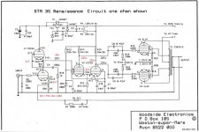
It isn't clear to me how that phase splitter can possibly work with such a low cathode resistance and equal plate resistors, and no balance pot like in the Renaissance STA-25. I dealt with a comparably modified Leak a while ago and it produced tons of 2HD, more than 10X the factory spec. I put it back to original condition and it went to factory spec.
the phase shifter is actually a pretty smart design. The triode is acting like a folded cascode with no voltage developed at the grid and cathode, only currents. So it has a high output impedance. the pentode has the grid as input signal and needs the extra pentode grid to increase the output impedance to make it more symmetrical to the triode.
Actually the STA25 has a regulation pot that the STA35 does not have but the valves are also different (in the annex a comparative image of the two diagrams)
before starting the project I had read in old contributions on the internet that the radford schemes technically would not have worked but instead they did it very well even though using a lot of NFB compensated by the excellent quality of the output transformers;
this story reminded me a lot of the famous story of the hornet "The wing structure of the hornet, in relation to its weight, is not suitable for flight, but he does not know it and flies anyway." 🙂
Attachments
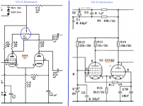
6U8 is identical with ECF82. And ECF82 was what radford used.Actually the STA25 has a regulation pot that the STA35 does not have but the valves are also different (in the annex a comparative image of the two diagrams)
before starting the project I had read in old contributions on the internet that the radford schemes technically would not have worked but instead they did it very well even though using a lot of NFB compensated by the excellent quality of the output transformers;
this story reminded me a lot of the famous story of the hornet "The wing structure of the hornet, in relation to its weight, is not suitable for flight, but he does not know it and flies anyway." 🙂
See Radford revisited
Also see STA25 schematics that seems to have more "conventional" resistor values and
a simpler preamp. All available at Redfordrevival
Last edited:
forgive me, my mistake6U8 is identical with ECF82. And ECF82 was what radford used.
I found another Sta35 schematic online (I can't figure out if it was done before or after the one I posted earlier).
in this diagram there is the pot mentioned above but instead of an ecc81 valve an ecc88 is mounted with the inevitable changes to the diagram
in this diagram there is the pot mentioned above but instead of an ecc81 valve an ecc88 is mounted with the inevitable changes to the diagram
Attachments
- Home
- Amplifiers
- Tubes / Valves
- Help and suggestions for my project based on the Radford STA-35 schematic