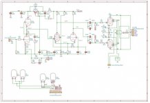
The triode is acting as a grounded-grid stage. The whole thing is a conventional Schmitt long-tailed-pair phase splitter, the difference from convention being that the LHS is a pentode, not a triode: this was done to extend HF response, as stated by Bailey when he described it.The triode is acting like a folded cascode with no voltage developed at the grid and cathode, only currents. So it has a high output impedance. the pentode has the grid as input signal and needs the extra pentode grid to increase the output impedance to make it more symmetrical to the triode.
The equations published by Schmitt show that it can never be balanced with such a low value of Rk and equal Rp values without a balancing pot. Leak in the Stereo 20 used Rk=23k, Rp1=91K, Rp2=100K. Mullard in the 5/20 used Rk=82K, Rp1=Rp2=100K which was still out of balance by 3%, which was less than the best resistor tolerance available in 1954: they only got as close as they did because Rk was already so high. The original 'real' Radford circuit as designed by Bailey uses Rk=8k2, Rp1=33K, Rp2=39K, taking into account that the pentode and triode sides may have different values of mu.
The missing pot must definitely be restored (or the original values above used, but this will change the grid voltage which alters the requirements of the previous stage).

Hello everybody.
unfortunately my eye problem has not improved and I have been hospitalized since Saturday.
the amplifier tests will unfortunately have to wait a little longer.
unfortunately my eye problem has not improved and I have been hospitalized since Saturday.
the amplifier tests will unfortunately have to wait a little longer.
Hello everybody,
I managed to do a few things:
I installed the EL34s and turned on the amplifier, as soon as the tubes go up to temperature the fuse blows ...
without the el34 the fuse does not blow, I took the opportunity to measure the voltage in the previous stages that I reported in the diagram.
I managed to do a few things:
- I unsoldered the coupling capacitors (C4, C4A1, C9 and C9A1).
- I replaced the 1 ohm resistors with 10 ohm ones (R8 and R10)
I installed the EL34s and turned on the amplifier, as soon as the tubes go up to temperature the fuse blows ...
without the el34 the fuse does not blow, I took the opportunity to measure the voltage in the previous stages that I reported in the diagram.
Attachments

HI,
On pin 5 reads -57 V. By rotating the trimmer the values go from -15 V to -57 V on both V1 and V2.
On pin 5 reads -57 V. By rotating the trimmer the values go from -15 V to -57 V on both V1 and V2.
Good.
Set the pot(s) to -57Volt. and install the EL34.
At this bias the EL34 should be totally cutoff, the only thing is that
the tubes would oscillate. This could happen if the screen connections are switched. If you have
an oscilloscope connect to one of the cathodes ( set to 1V/div) before power up.
If no oscillation, slowly turn bis up until 40mA / tube.
I insert the el34 tubes.
I start the heaters and I waited until they reaches the operative temperature
I give voltage to the bias and check with multimeter -57v on pin 5 of both tubes.
On the cathode resistors I always read 0v even by varying the value of the bias voltage.
Place the oscilloscope on pin 8 and I read absolutely nothing.
I start the high voltage and the fuse blows immediately.
I am doing all these tests without coupling capacitors installed.
In your schematic the colors of the taps of the secondary of the output transformer don't match the colors of the leads of your output transformer shown in some of the pictures you linked to in post #1. Are you sure you correctly 'translated' the colors of the schematic to the colors of the output transformer?
I agree. There is a problem with the circuit not corresponding to the schematics. The neddlesslyIn your schematic the colors of the taps of the secondary of the output transformer don't match the colors of the leads of your output transformer shown in some of the pictures you linked to in post #1. Are you sure you correctly 'translated' the colors of the schematic to the colors of the output transformer
complicated startup obscures the problem.
If a adjustable DC power for the B+ is not available then get a 10k 5-25w resistor and
install between B+ and the output transformer. This will make possible taking DC
readings.
Also disconnect the screens from the relay ( disconnect all connections to the relay) and connect
direct to the transformer, there is a non zero possibility that the relay shorts to ground.
Turn on only B+, there should not draw current as the tubes are cold. if current is drawn
identify and fix.
In my post #49 "secondary" should read "primary" since only the colors of the primary connection are shown on the schematics.
I removed the relay and connected the output transformer directly, even in this condition when I give voltage the fuse blows. I ordered a 10k 25w resistor and it should arrive in the next few days.
The Toroidy transformer has different primary colors than those I had indicated on the diagram, following the conversion schematic / O.T. :
The Toroidy transformer has different primary colors than those I had indicated on the diagram, following the conversion schematic / O.T. :
- A1 blue / green
- green / blue
- VAA red / black
- yellow / red
- A2 brown / yellow
Attachments

Ok, then the relay is free from guilt.
With the resistor mounted at the B+ source , turn on all voltages . The intention with the resistor
is that the fuse won't blow but the voltage may be measured at all times. AT power on
the voltage should be same as B+ from the PSU as the tubes don't conduct at once.
check the voltage during power on.
I received and installed the 10k resistor between B + and the output transformer.
I connect the oscilloscope between ground and pin 8 and I give voltage, this thick fuse does not blow and on the instrument I do not see oscillations but a continuous voltage equal to the one I read with the multimeter on the test points.
The resistor 10k has warmed up much, these are the tensions that I measured, B + of the resistor is detected before 450v, read on pin 3 of thr EL34 was 8v ..
Last edited:
Fine, now you can take measurment, at least in a short time, to diagnose.I received and installed the 10k resistor between B + and the output transformer.
I connect the oscilloscope between ground and pin 8 and I give voltage, this thick fuse does not blow and on the instrument I do not see oscillations but a continuous voltage equal to the one I read with the multimeter on the test points.
The resistor 10k has warmed up much, these are the tensions that I measured, B + of the resistor is detected before 450v, read on pin 3 of thr EL34 was 8v ..
8Volt on the cathode across 10ohm , thats 800mA.
Does this happen before filament is warm ? Or does it ramp up while filament warms up ?
You got no AC/oscillation, fine. Whats the voltage on all other pins
1 (g3 )
3(a)
4(g2)
5(g1)
8(k)
and is there DC on the filament ( pin 2 and 8 ) ?
/PS
Are you sure you count pin numbers on the octal sockets the right way ?
/DS
Hello to all, the values published the other day they should not be considered because I found a wrong connection.
I have now repeated the measurement and these are the DC values measured with respect to GND.
V1
Pin1 0.120v cold, warm 0,38v
Pin2 6.3v
Pin3 cold 450v, 405v 350V-hot
Pin4 cold 450v, 350V-405 hot
Pin5 -56v cold, warm -48
Pin6 0v
Pin7 0v
Pin8 0.120v cold, warm 0,38v
V2
Pin1 0v cold, warm 0,004v
Pin2 6.3v
Pin3 cold 450v, 405v 350V-hot
Pin4 cold 450v, 350V-405 hot
Pin5 -56v
Pin6 0v
Pin7 0v
Pin8 0v cold, warm 0.004
I tried to change the valves and this couple find equal values for both the various pins.
These measures are being compared to GND:
Pin1 0v cold, warm 0v
Pin2 6.3v
Pin3 cold 465v, 456v hot
Pin4 cold 465v, 456v hot
Pin5 -57v cold, warm -57
Pin6 0v
Pin7 0v
Pin8 0v cold, warm 0v
The 10k resistor installed in series to B + remains cool while rotating the trimer of the bias values detected on pins 1 and 8 do not vary always remaining at 0v.
Pin 1(g3) and 8 (k) should stay at 0V since the tubes are in "cutoff".
Now turn the bias adjustment(s) until you see pin8 starting to increase,
i understand that the cathode resistor is 10 ohm, thus 0.4V could be a good starting point.
( you should probably remove the 10k B+ resistor by now )
Now turn the bias adjustment(s) until you see pin8 starting to increase,
i understand that the cathode resistor is 10 ohm, thus 0.4V could be a good starting point.
( you should probably remove the 10k B+ resistor by now )
What was connected wrong than? Since you are using circuit boards, there can't be that many possible wrong connections.Hello to all, the values published the other day they should not be considered because I found a wrong connection.
This is puzzling to me since it seems to indicate a problem that is not directly related to the EL34's....
I tried to do a ignition without the NFB connected and without the ECC81 and PCF82 tubes, so with only the EL34s mounted, in this case the fuse did not blow.
...
Also puzzling to me is that adjusting the bias trim pots seemed to work in post #46 (adjustable from -57 V to -15 V) but that adjusting them in post #57 didn't cause any voltage drop over the 10 Ohm cathode resistors.
In your post #1 you wrote that you designed the circuit board(s) yourself and had them made by JLCPCB. Could you post the gerber files and/or clear and detailed pictures of the circuit board(s) so that they can be checked by forum members?
It works!!! I was able to adjust the bias.
with hot tubes I set the bias to 0.385 V (B + 408V) and at least by ear it seems to sound very good, what measures do you recommend me to do with the oscilloscope?
if instead I set the triode mode it starts to oscillate voluntarily, suggestions?
What was the problem? the real thing is that I'm an idiot and working on PCB has deceived me;
I made a mistake during the mirror phase to move the component from the bottom to the top side and the pins were numbered backwards compared to those of the el34 so it was all upside down (I started to burn the tubes)
pin 1 was pin 8
pin 2 was pin 7
pin 3 was pin 6
pin 4 was pin 5
pin 5 was pin 4
pin 6 was pin 3
pin 7 was pin 2
pin 8 was pin 1
not bad for pins 1-8 and 2-7 but for the others .........😱😱😱😱😱😱
attached the current gerber file (not to be used as they are not working) in the next few days I will try to update the files and I would like to make them available to everyone on the forum.
currently the PCB has the following problems:
I thank everyone again for the help you have given me so far.
with hot tubes I set the bias to 0.385 V (B + 408V) and at least by ear it seems to sound very good, what measures do you recommend me to do with the oscilloscope?
if instead I set the triode mode it starts to oscillate voluntarily, suggestions?
What was the problem? the real thing is that I'm an idiot and working on PCB has deceived me;
I made a mistake during the mirror phase to move the component from the bottom to the top side and the pins were numbered backwards compared to those of the el34 so it was all upside down (I started to burn the tubes)
pin 1 was pin 8
pin 2 was pin 7
pin 3 was pin 6
pin 4 was pin 5
pin 5 was pin 4
pin 6 was pin 3
pin 7 was pin 2
pin 8 was pin 1
not bad for pins 1-8 and 2-7 but for the others .........😱😱😱😱😱😱
attached the current gerber file (not to be used as they are not working) in the next few days I will try to update the files and I would like to make them available to everyone on the forum.
currently the PCB has the following problems:
- Pinout el34 on PCB (solved but file needs to be updated)
- Oscillations in triode mode.
- 6.3 v DC power supply, now it works and remains regulated but the resistances and the integrated circuit heat up a lot.
I thank everyone again for the help you have given me so far.
Attachments
- Home
- Amplifiers
- Tubes / Valves
- Help and suggestions for my project based on the Radford STA-35 schematic