Hi thanks for the kind and helpful advice I tend to like simpler designs With less parts i mean The minum to get a decent and stable result.I guess the 42-0-42 winding is a real CT'ed one that you cant't separate/isolate. OTOH, why getting rid of an advantageous split rail supply? There are many amplifier designs that fit. I'd recommend the Honeybadger.
Best regards!
I am very bad at doing things ... i can just assemble kits and modules A mistake is around the corner.
Yes there are many kits working with half that 116 Volt One thing i have learned clearly For small power better to use smaller raill voltagesJust use a two diode rectifier if it’s connected in the center and can’t be easily unconnected. Eliminate the two diodes and cap on the negative half. That’s the way they used to do it with tube rectifiers (Because common cathodes are easy, common anodes are not).
Why eliminate the split rail? If you didn‘t want to work with the full 116 volts - something safer the first time out of the chute. There are plenty of designs out there that can be copied either way.
This is very very important for me to know
I was thinking to get a dual voltage from those 116V .... it would be perfect But i do not know if this transformer is center tapped or there are two separate secondaries connected on one wire to get the 0 To get a dual voltage from each secondary would be perfect
I am sorry but i dont understand what you are suggesting 😕

i may be out to lunch on this one and would like to hear from others as to the reason that this amp failed because of where the bias transistors where located on the heatsink or is that just me ....
https://www.diyaudio.com/community/attachments/noiz-hercules-180-jpg.1046465/
https://www.diyaudio.com/community/attachments/noiz-hercules-180-jpg.1046465/
hi the previous owner told me that he opened and cleaned it from dusti may be out to lunch on this one and would like to hear from others as to the reason that this amp failed because of where the bias transistors where located on the heatsink or is that just me ....
https://www.diyaudio.com/community/attachments/noiz-hercules-180-jpg.1046465/
at the power up it smoked badly from one channel and i can see some parts roasted
in the meantime and with all you great help i have decided to keep only the chassis for future kits
as i said i have finally understood that the higher the rail voltages the higher the risks
i just need some 20 or 30 W of power but with good tolerance of low impedance
a +/- 30 VDC should be enough for me
Of course i also understand that when high power is needed also high rail voltages are a must
About class A it needs big heat sink so this one is undersized I will stay with class AB
I will search in the forum for low power good sound projects
For sure I will answer to all the post above this
I am finishing my damned relocation to a new place and it makes me mad
Thank you All so much for now
gino
Hi its me again. This is what i meant for simpler project. And you say that you like the sound ? i am a little esitant about a cap at the outputHere is an amp I have built that uses a single rail of 50 to 70 volt. One side of your transformer would be 58.4 v. https://www.diyaudio.com/forums/solid-state/236256-retro-amp-50w-single-supply-42.html
The artwork is on page 1 or revised on the last page. My point to point build is on page 21. You could put 2 channels parallel on one side of that transformer. Harmonic distortion sims at less than .2%. Mine at 70 v rail measured 70 w output for 5 seconds both sides on a 475 VA transformer. I have a single 3300 uf 80 v cap running both sides, and two 3300 uf 80 v speaker caps. On a 58.4 v rail you could use 63 v caps which are easier to find.
My post on p21 shows easier to find (in the US) transistors although I've upgraded the TIP41c/42c drivers to MJE15028/29 for better high frequency sound.
I read some criticism. Like for transformer couple amps
Thanks a lot again. I think i will keep only the chassis in the end. This transformer is not the best option for what i have in mind That is a small power ampI don't believe you have room in your case for honeybadger. It has 5 pairs output transistors per channel, you have 2 pairs per channel. I've never built one, none of my salvage cases was big enough except one with +-85 supply.
You're stuck with +-58.4 windings (42 * 1.4) plus low current +-15 winding unless you buy a new transformer. Using one winding for two capacitor coupled 50 w amp pcbs is one option.
Your heat sink is drilled for 4 - 2.4 cm wide transistors. Drilling it for something else requires skill. You might do better buying two of your ebay/amazon/alibaba pcbs for that configuration and a dual winding 24 or 30 v 200 VA transformer. OTOH bad solder joints make split supply amps burn speaker windings. New people make bad solder joints. One solution is two speaker protection boards, of which most examples for sale are snake oil (under sized AC rated relays that won't break a DC arc). The other solution is the speaker capacitor amp, which uses an extremely reliable $3 capacitor to block off DC. Unfortunately, nobody on ebay I know of is selling pcbs for speaker capacitor amps. You have to take a gerber file off a thread like I linked to above, send that file to a PCB house, and get them to make a couple of samples yourself. Then you have to drill it yourself.
Even only power amp. Because i have plan for a line preamp in the future. I need just few clean watts
I was looking at the Nelson Pass projects but they are all class A and need big heath sink
I find the Honeybadger too complex for a first project Too many parts I was thinking to something like this ...The Honeybadger has tree power transistor pairs per channel. Anyway, the existing heatsinks would need to be checked if they're wide enough. There's a drill template somewhere to check this.
Best regards!
Edit: Ok, according to the pic in #12, the sinks don't fit.
https://www.diyaudio.com/community/threads/thoughts-on-the-velleman-k8060.180220/
but then i read very bad opinions in the forum
Very nice amps and big too As i dont need much power 3 output pairs for channel seem too many After all this amp was able to output big power with just a pair of bjts per side All the high power amps i have seen in the web have rows of many bjts or mosfets I think they have designed it badlyYou don’t necessarily NEED to order PCBs - here are a couple of cap coupled amps built on perf boards. One is pretty big. If you are going to build a split supply honey badger, I’d definitely order boards to minimize the chance of mishap. Preferably all-in-one boards with a DC protect built in (not outboard). Cap coupled amps are immune to some forms of mishap - and the only thing I’d trust to perf board construction.
Yes ! unfortunately the outputs is too high ... i will keep the chassis It is already something They do not come cheap and there is also some heat sinkThe transformer is the only thing which seems useful.
Dispose of it, and build another one from scratch?
Unfortunately i cannot use the two secondaries separated It is a V-0-V type It is quite big actually I do not think it is broken
I find at 1/8 to 70 watts, AX6 sounds the same on SP2-XT speakers as Peavey CS800s rated at .03% HD (harmonic distortion) @ 240 w/ch. No capacitors in sound path of CS800s with XLR input. Speaker capacitor causes phase shift, but much less effect than the walls floors & furniture in your room.Hi its me again. This is what i meant for simpler project. And you say that you like the sound ? i am a little esitant about a cap at the output
I read some criticism. Like for transformer couple amps
I think people that claim they can hear difference between .2% HD and .0003% HD on speakers are hallucinating. Speakers produce .5% to 20% HD. I have a pair of speakers now that are rated 2nd & 3rd harmonic distortion 20 db down from sound @ 5 w. SP2(2004) . Speakers is where I spend my money, not the amp. The amp chassis was $50, the parts to build AX6 about $40. I built AX6 point to point on NemaCE 1/16" board (garolite). I use 1/4" air tubing as stand offs around #6 screws. Only about 70 wires, 6 transistors, very simple amp. AX6 responds well to regulated power supply rail, which my amp chassis (dynakit ST120) came with.
Having $300 (used) speakers is one reason I am passionate about speaker protection against DC. I've blown 2 speakers in the past, one of $240 a pair LWEIII (1974) and one of $200 a pair KLH23 (1978). That was with a transformer coupled vacuum tube amp.
I have some transformer coupled amps too, MMA-875t. Bass rolls off 3 db below 50 hz but I can't hear much difference on those either. HD <.5%. 75 w monaural. Cheaper than dirt, got one for $20 +$26 freight. Working.
Simple.Yes there are many kits working with half that 116 Volt One thing i have learned clearly For small power better to use smaller raill voltages
This is very very important for me to know
I was thinking to get a dual voltage from those 116V .... it would be perfect But i do not know if this transformer is center tapped or there are two separate secondaries connected on one wire to get the 0 To get a dual voltage from each secondary would be perfect
I am sorry but i dont understand what you are suggesting 😕
Attachments
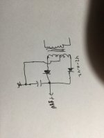
You can use the transformer to drive 0-42 for many chip amps, even 1875 and maybe 3886. Use each side 0-42 per channel.
Transformers are expensive, and obtaining chassis and heat sinks is also a headache.
I suggest you check out the transformer with a meter for impedance and leakage to body, and keep the whole thing in storage.
If it is good, you do get kits (populated PCBs) to wire in and use.
The mounting and connection is all you need to do.
I think we need to understand what the OP needs. It may not even be necessary to bloat the request to an oversized monster amp, just to make use of the inappropriate transformer. He can do what he really wants with no more than a little 25/25V 120VA toroid or conventional 48V CT transformer here so let's not suggest designs powerful enough to wake the neighbours a half kilometre away.I am mainly focusing 40-50W/8 Ohm amps with very simple circuits.........Max power is not an issue as i said above
I need few very clean and robust watts.
Last edited:
- Home
- Amplifiers
- Solid State
- Using parts from a dead amp