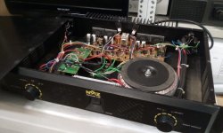
Hi Everyone ! i have bought an amp with a dead channel Its name is Noiz Hercules 180
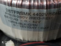
There is a big 42-0-42 transformer inside (see pic attached) that i would like to try to reuse with the chassis
It would be a pity to throw it directly in the garbage bin
It must be at least a 500VA thing
I found interesting the L7 mosfet amp kit but then i read in this excellent forum about possible issues when operated at high voltages
A kit as simple as possible could be my first DIY attempt
Thank you very much for any kind and welcome suggestion
Kind regards,
gino
Attachments
Last edited:
Rebuilding an amp using an existing chassis and transformer is common and gives you a good head start. You just need a circuit that will use the power supply voltages that the transformer is suited for. Another way out is to design a regulator board and regulate the voltages down to what you need, if too high.

I suggest you take a look at this amplifier. Your transformer with an Ideal rectifier power supply should provide about +52/-52 V needed for this amp.
https://www.diyaudio.com/community/...onscious-100w-class-ab-for-lean-times.353512/
Excellent performance and relatively inexpensive parts. I don’t know how big your heatsinks are, so check that.
https://www.diyaudio.com/community/...onscious-100w-class-ab-for-lean-times.353512/
Excellent performance and relatively inexpensive parts. I don’t know how big your heatsinks are, so check that.
At the very least recycle the copper, its valuable these days...It would be a pity to throw it directly in the garbage bin
The source amp is rated for 2 x 180W into 4 ohms, so that transformer should definitely in the 500VA or so region
Hi thank you very much and sorry for the late reply. I am in the middle of moving to a new flat.Rebuilding an amp using an existing chassis and transformer is common and gives you a good head start. You just need a circuit that will use the power supply voltages that the transformer is suited for. Another way out is to design a regulator board and regulate the voltages down to what you need, if too high.
I have to say that the high VAC out is a problem for me. I am mainly focusing 40-50W/8 Ohm amps with very simple circuits
I like the idea to supply even 200W output bjts with low voltage like 30V to stay in the SOA more easily A higher supply voltage is stressing more them
Max power is not an issue as i said above I need few very clean and robust watts
I have to look at the high current regulators issue that i have never looked at.
I am still evaluating possibilities to save this big transformer from the garbage
Thanks again, gino
Hi thank you very much for the valuable advice. The amp looks really great 😍I suggest you take a look at this amplifier. Your transformer with an Ideal rectifier power supply should provide about +52/-52 V needed for this amp.
https://www.diyaudio.com/community/...onscious-100w-class-ab-for-lean-times.353512/
Excellent performance and relatively inexpensive parts. I don’t know how big your heatsinks are, so check that.
I am still undecided about taking the challenge to repair the faulty channel But the lack of a schematic does not help of course
I see some burnt parts very clearly and other i do not see
I am very ignorant and i have a big question Can the parts be tested without desoldering them from the board ? that would help
Anyway i am saving this thread for future reference From May on i will be more free to work I am in the middle of a moving
Thanks a lot again, gino
Hi ! thank you very much for your kind reply and advice.At the very least recycle the copper, its valuable these days...
The source amp is rated for 2 x 180W into 4 ohms, so that transformer should definitely in the 500VA or so region
If i understand well the VA rating of a mains transformer fixes the max power that an amp can deliver ?
just to set a method .... can i say that i take the power transformer VA rating (that i can derive from the max power consumption reported on the back of the amp) divide it by 2 and i get the power on 4 ohms (for both channels summed)?
just to get a broad idea of the max power available
I see many commercial medium power integrateds these days coming with max 200VA max power consumption written on the back of the units
This should mean around 100W of max total output power and about 50W/channel on 4 ohm ?
Not that great as as max current actually ... like 3.5A no more
For sure they look nice ... but i prefer substance than look
P.S. by the way on the back there is written 5A fuse ... and we have 230VAC here in Italy This would mean more than 1kW of max power consumption 😵
Maybe a lower and faster fuse would have save the amp ?
Last edited:
No.Maybe a lower and faster fuse would have save the amp ?
Better heat sinking or better fans saves amps. Short detection (VI limiter) saves amps. Thermal shutdown on heat sink saves amps. Adequate number of output transistors to match the power supplied saves amps. Good modeling of soa violations feeding the VI limiter saves amps. Disconnect of speakers from output transistors on short detection saves amps.
Rails of this transformer would be +-58.4 v Class AB voltage swing would be ~29 vac. Into 8 ohm that would be 3.7 A. SOA of a MJ15024/25 is about 2 amps, so at least 2 pairs of these as output transistors would be required to meet DC soa spec. 3 pairs would be safer. 2sa1943/2sc5200 used more commonly in Europe, those are only about 1.5 A soa so 3 or 4 pairs would be required.
Most consumer amps don't have the protection features. Some PA amplifiers do. The price of used PA amps with transformers in blown condition is minimal, because touring bands don't want to carry the weight. You may not be allowed to buy blown amps in Europe, however.
Hi ! thank you so much for your very kind and precious advice.No.
Better heat sinking or better fans saves amps. Short detection (VI limiter) saves amps.
Thermal shutdown on heat sink saves amps. Adequate number of output transistors to match the power supplied saves amps. Good modeling of soa violations feeding the VI limiter saves amps. Disconnect of speakers from output transistors on short detection saves amps.
Rails of this transformer would be +-58.4 v Class AB voltage swing would be ~29 vac. Into 8 ohm that would be 3.7 A. SOA of a MJ15024/25 is about 2 amps, so at least 2 pairs of these as output transistors would be required to meet DC soa spec. 3 pairs would be safer. 2sa1943/2sc5200 used more commonly in Europe, those are only about 1.5 A soa so 3 or 4 pairs would be required.
Most consumer amps don't have the protection features. Some PA amplifiers do. The price of used PA amps with transformers in blown condition is minimal, because touring bands don't want to carry the weight. You may not be allowed to buy blown amps in Europe, however.
I understand now much better things that i had only imagined before your reply.
On this basis i dare to say that this is a badly designed amp if high voltage rails need more output devices in parallel to allow for safe operations.
Even in the remote case i could be able to repair it (almost a mission impossible) i would end always with a badly conceived amp.
I am sorry but i am also happy to have fixed some points.
When low power is the aim high voltage rails are a non sense technically speaking This is very important to me.
As i said before i do not really need many watts as i listen at low levels with 87-88 dB speakers. Robust 20-30 W/channel would suffice.
Would it be a sane idea to use another transformer downstream the original one (with the original maybe placed outside in a box to free space inside the cabinet) to get lower rail voltages and try one low power kit ?
I really need to get a kit to have some hopes to end the project. And if so which one ?
I prefer not class A I am sure that decent sound can be obtained also from class AB design Almost sure lets say
Thank you sincerely again. As i said i have fixed some important points now. 🙂
Kind regards,
gino 🤓
That trafo would normally be used on a 150 watt per channel amplifier. Two pairs of metal or three pairs of plastic outputs is correct - if running low impedance loads bump it up by one more. The Crown DC300A used 4 pairs of metal outputs for down to 2 ohms. If that’s too many or too much - consider building an amp that runs off a single 58 volt rail. People tend to shy away from cap coupled outputs, but with the quality of today’s electrolytics there is no reason not to. Especially at lower power. You can still make a very good sounding amplifier, needing only one pair of outputs if at least 200W units are used (or two pairs of the little ones per channel). Providing enough power for normal use, and generating less heat. Also less chance of a newbie mistake burning the house down or destroying $100 worth of parts. If you were inclined to run it class A (still requiring large heat sinks and multiple output pairs), it would at least be possible. The trafo would be undersized to run class A at the full 116 volt rail to rail.
Here is an amp I have built that uses a single rail of 50 to 70 volt. One side of your transformer would be 58.4 v. https://www.diyaudio.com/forums/solid-state/236256-retro-amp-50w-single-supply-42.html
The artwork is on page 1 or revised on the last page. My point to point build is on page 21. You could put 2 channels parallel on one side of that transformer. Harmonic distortion sims at less than .2%. Mine at 70 v rail measured 70 w output for 5 seconds both sides on a 475 VA transformer. I have a single 3300 uf 80 v cap running both sides, and two 3300 uf 80 v speaker caps. On a 58.4 v rail you could use 63 v caps which are easier to find.
My post on p21 shows easier to find (in the US) transistors although I've upgraded the TIP41c/42c drivers to MJE15028/29 for better high frequency sound.
Hi ! thank you very much indeed for your valuable advice. I have an important questionThat trafo would normally be used on a 150 watt per channel amplifier. Two pairs of metal or three pairs of plastic outputs is correct - if running low impedance loads bump it up by one more. The Crown DC300A used 4 pairs of metal outputs for down to 2 ohms. If that’s too many or too much - consider building an amp that runs off a single 58 volt rail. People tend to shy away from cap coupled outputs, but with the quality of today’s electrolytics there is no reason not to. Especially at lower power. You can still make a very good sounding amplifier, needing only one pair of outputs if at least 200W units are used (or two pairs of the little ones per channel). Providing enough power for normal use, and generating less heat.
Could an amp designed to be powered with a dual supply run with a single supply provided that a cap at the input and another at the output are used ? that would increase the options number Many low power kits work on +/- 30V
I know that old amps were cap coupled and people tend to like their sound Maybe some nice HD ?
Very good indeed. I have understood that amps can set on fire a house I read bad stories in the web I think it was about a very low impedance speaker acting almost as a short circuit Of course the amps able to drive it deserve a great respectAlso less chance of a newbie mistake burning the house down or destroying $100 worth of parts.
No class A Maybe i am wrong but considering that very decent sound can be obtained from class AB amps i do not see the reason to go class AIf you were inclined to run it class A (still requiring large heat sinks and multiple output pairs), it would at least be possible. The trafo would be undersized to run class A at the full 116 volt rail to rail.
Thank you very much again I would like to start with a kit It will be my first experience in making something In the past i just replaced some parts on a pcb of an old vintage solid state amp I bought a desoldering machine to do that as clean as possibleHere is an amp I have built that uses a single rail of 50 to 70 volt. One side of your transformer would be 58.4 v. https://www.diyaudio.com/forums/solid-state/236256-retro-amp-50w-single-supply-42.html
The artwork is on page 1 or revised on the last page. My point to point build is on page 21. You could put 2 channels parallel on one side of that transformer. Harmonic distortion sims at less than .2%. Mine at 70 v rail measured 70 w output for 5 seconds both sides on a 475 VA transformer. I have a single 3300 uf 80 v cap running both sides, and two 3300 uf 80 v speaker caps. On a 58.4 v rail you could use 63 v caps which are easier to find.
My post on p21 shows easier to find (in the US) transistors although I've upgraded the TIP41c/42c drivers to MJE15028/29 for better high frequency sound.
A kit will give me more chance to succeed
I have a question This transformer is 42-0-42 Can i get two separate dual powe supply from its secondaries ? i mean connecting two wires to the O output of the transformer and send one to a channel and the other to the other channel with two diodes bridges one per channel
Just use a two diode rectifier if it’s connected in the center and can’t be easily unconnected. Eliminate the two diodes and cap on the negative half. That’s the way they used to do it with tube rectifiers (Because common cathodes are easy, common anodes are not).
Why eliminate the split rail? If you didn‘t want to work with the full 116 volts - something safer the first time out of the chute. There are plenty of designs out there that can be copied either way.
Why eliminate the split rail? If you didn‘t want to work with the full 116 volts - something safer the first time out of the chute. There are plenty of designs out there that can be copied either way.
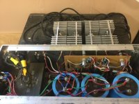
I don't believe you have room in your case for honeybadger. It has 5 pairs output transistors per channel, you have 2 pairs per channel. I've never built one, none of my salvage cases was big enough except one with +-85 supply.
You're stuck with +-58.4 windings (42 * 1.4) plus low current +-15 winding unless you buy a new transformer. Using one winding for two capacitor coupled 50 w amp pcbs is one option.
Your heat sink is drilled for 4 - 2.4 cm wide transistors. Drilling it for something else requires skill. You might do better buying two of your ebay/amazon/alibaba pcbs for that configuration and a dual winding 24 or 30 v 200 VA transformer. OTOH bad solder joints make split supply amps burn speaker windings. New people make bad solder joints. One solution is two speaker protection boards, of which most examples for sale are snake oil (under sized AC rated relays that won't break a DC arc). The other solution is the speaker capacitor amp, which uses an extremely reliable $3 capacitor to block off DC. Unfortunately, nobody on ebay I know of is selling pcbs for speaker capacitor amps. You have to take a gerber file off a thread like I linked to above, send that file to a PCB house, and get them to make a couple of samples yourself. Then you have to drill it yourself.
Last edited:
The Honeybadger has tree power transistor pairs per channel. Anyway, the existing heatsinks would need to be checked if they're wide enough. There's a drill template somewhere to check this.
Best regards!
Edit: Ok, according to the pic in #12, the sinks don't fit.
Best regards!
Edit: Ok, according to the pic in #12, the sinks don't fit.
Last edited:
You don’t necessarily NEED to order PCBs - here are a couple of cap coupled amps built on perf boards. One is pretty big. If you are going to build a split supply honey badger, I’d definitely order boards to minimize the chance of mishap. Preferably all-in-one boards with a DC protect built in (not outboard). Cap coupled amps are immune to some forms of mishap - and the only thing I’d trust to perf board construction.
Attachments

- Home
- Amplifiers
- Solid State
- Using parts from a dead amp