Good morning everyone,
After building a clone of the kondo M77, which is electrically finished but I haven't built the case yet (don't worry I'll report my experience in the dedicated post https://www.diyaudio.com/community/threads/kondo -ksl-m77-phone-preamp-clone-project.358732/page-4 ),
, I decided to build a tube power amplifier.
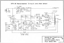
It all started when I read this Italian article in which the author builds a replica of the Radford STA-35. https://blog.ampliekit.it/index.php/i-nostri-kit/14-kh-021-radford-sta-35-dual-mono ,
i decided to draw the schematics on fusion360 then i generated the gerber files and finally i had the PCBs made by JLCPCB.
Attached you will find the wiring diagrams and some photos of the finished board.
Everyone ready!!! I connect the power transformer, the output transformers, I connect an 8 Ω resistor as a load on the secondary of the TU and I make voltage without valves (the TU is produced by Toroidy.pl and I attach the photos)
It didn't explode !! All tensions are fine.
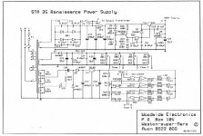
I decide to insert the valves, I only turn on the resistors and the first problem arises, the integrated LT1084 which stabilizes the 6.3V heats a lot and cannot manage the 3.3 A of the final valves and the pre valve, I turn everything off, I repeat the calculations and I order a dropping resistor (RW3 in the diagram).
To continue the tests, the power supply terminates with an external 6.3V transformer and now the temperatures are under control.
This time I turn on all the power supplies and immediately the high voltage "B +" fuse blows (go to the diagram), I discharge the capacitors, change the fuse and try again but the fuse blows again (the project fuse is a 0, 15 AT)
I check all the circuit and components and they all seem ok to me, I give voltage without the power tubes and the fuse does not burn, I tried to change the power tubes, and with all the fuses they blow (2 + 2 EL34 Tung-sol and 2 JJ).
If I measure the voltages on the power amp sockets without the tubes mounted and with the bias at zero I read the following values:
PIN 3 465V
PIN 4 465V
PIN 5 -59V
Do you have any suggestions as to why this happens? i'm going crazy to fix this and can't find a solution.
You can find the wiring diagrams and photos at the following link
https://drive.google.com/drive/folders/17wr34KiBkkMsO7Md7qEI8U4RoYIbVnn6
Thanks a lot to everyone in advance
PS in a moment of desperation I fitted a 1A fast fuse and that too blew.
Luca
After building a clone of the kondo M77, which is electrically finished but I haven't built the case yet (don't worry I'll report my experience in the dedicated post https://www.diyaudio.com/community/threads/kondo -ksl-m77-phone-preamp-clone-project.358732/page-4 ),
, I decided to build a tube power amplifier.
It all started when I read this Italian article in which the author builds a replica of the Radford STA-35. https://blog.ampliekit.it/index.php/i-nostri-kit/14-kh-021-radford-sta-35-dual-mono ,
i decided to draw the schematics on fusion360 then i generated the gerber files and finally i had the PCBs made by JLCPCB.
Attached you will find the wiring diagrams and some photos of the finished board.
Everyone ready!!! I connect the power transformer, the output transformers, I connect an 8 Ω resistor as a load on the secondary of the TU and I make voltage without valves (the TU is produced by Toroidy.pl and I attach the photos)
It didn't explode !! All tensions are fine.
I decide to insert the valves, I only turn on the resistors and the first problem arises, the integrated LT1084 which stabilizes the 6.3V heats a lot and cannot manage the 3.3 A of the final valves and the pre valve, I turn everything off, I repeat the calculations and I order a dropping resistor (RW3 in the diagram).
To continue the tests, the power supply terminates with an external 6.3V transformer and now the temperatures are under control.
This time I turn on all the power supplies and immediately the high voltage "B +" fuse blows (go to the diagram), I discharge the capacitors, change the fuse and try again but the fuse blows again (the project fuse is a 0, 15 AT)
I check all the circuit and components and they all seem ok to me, I give voltage without the power tubes and the fuse does not burn, I tried to change the power tubes, and with all the fuses they blow (2 + 2 EL34 Tung-sol and 2 JJ).
If I measure the voltages on the power amp sockets without the tubes mounted and with the bias at zero I read the following values:
PIN 3 465V
PIN 4 465V
PIN 5 -59V
Do you have any suggestions as to why this happens? i'm going crazy to fix this and can't find a solution.
You can find the wiring diagrams and photos at the following link
https://drive.google.com/drive/folders/17wr34KiBkkMsO7Md7qEI8U4RoYIbVnn6
Thanks a lot to everyone in advance
PS in a moment of desperation I fitted a 1A fast fuse and that too blew.
Luca
Attachments
Last edited:
On one of your photo's I see a part with "Axicom" written on it. As far as I know, Axicom makes relais. If it is indeed a relay on your board, why is it not on the schematics? Are there other parts on your boards that are not on the schematics?
The measured 465 V is pretty high (it exceeds the 450 V of C5 and C6 in the power supply) but it's measured without the EL34's in place. With them drawing current. the 465 V will drop somewhat.
I'm surprised about the ECC81 in srpp mode with a B+ of only 82 V, resulting in each triode section working with a little under 41 V between cathode and anode, at an estimated bias of only -0.7 V.
I would use a dedicated variable DC supply as B+, slowly increasing while taking
measurments and watching current flow.
I would also disconnect the nfb until full B+ is there and bias have been adjusted
( if NFB has wrong phase the amp will oscillate AND draw lots of power )
measurments and watching current flow.
I would also disconnect the nfb until full B+ is there and bias have been adjusted
( if NFB has wrong phase the amp will oscillate AND draw lots of power )
forgive me, I uploaded the wrong drawings, on the first post now there are the correct ones.On one of your photo's I see a part with "Axicom" written on it. As far as I know, Axicom makes relais. If it is indeed a relay on your board, why is it not on the schematics? Are there other parts on your boards that are not on the schematics?
The measured 465 V is pretty high (it exceeds the 450 V of C5 and C6 in the power supply) but it's measured without the EL34's in place. With them drawing current. the 465 V will drop somewhat.
I'm surprised about the ECC81 in srpp mode with a B+ of only 82 V, resulting in each triode section working with a little under 41 V between cathode and anode, at an estimated bias of only -0.7 V.
The relay is used to switch from ultralinear to triode mode. the capacitors I used all have values higher than those in the diagram (for example AC5 is a 800v pp).
With regard to the B + of the ecc81 valve, also in the original scheme it is stabilized at 81-82v.
Attachments
as soon as possible I will try to turn it on again with the NFB disconnected to see what happens.I would use a dedicated variable DC supply as B+, slowly increasing while taking
measurments and watching current flow.
I would also disconnect the nfb until full B+ is there and bias have been adjusted
( if NFB has wrong phase the amp will oscillate AND draw lots of power )
I will also try to figure out how to slowly make B + rise.
In the new schematics in post #1 (which changed into Italian...) I see that the heaters of the ECC81 + 2 x EL34 were running from the same source (one LT1084). What I understand of your description is that this didn't work. I don't see how RW3 fits in your description since that resistor is involved in heating the PCF82 only, but maybe that was a typo.
Now you are using an extra 6.3 V transformer for the heaters of the EL34's (and of the ECC81's?). Did you earth this extra filament supply?
You describe one fuse blowing. But aren't there two fuses, one for each channel? And if so, do they both blow?
Now you are using an extra 6.3 V transformer for the heaters of the EL34's (and of the ECC81's?). Did you earth this extra filament supply?
You describe one fuse blowing. But aren't there two fuses, one for each channel? And if so, do they both blow?
I have quickly updated the scheme erroneously calling two resistors with the same name, original RW3 is used to regulate the 9.5 v of the PCF82 valve as you said correctly, there is another resistor RW3 (which from now we will call RW9) that should lower the input voltage on U2_ECC81 / EL34_6.3V.In the new schematics in post #1 (which changed into Italian...) I see that the heaters of the ECC81 + 2 x EL34 were running from the same source (one LT1084). What I understand of your description is that this didn't work. I don't see how RW3 fits in your description since that resistor is involved in heating the PCF82 only, but maybe that was a typo.
Now you are using an extra 6.3 V transformer for the heaters of the EL34's (and of the ECC81's?). Did you earth this extra filament supply?
You describe one fuse blowing. But aren't there two fuses, one for each channel? And if so, do they both blow?
Approximately 15V no-load in input to U2_ECC81 / EL34_6.3V, so the voltage difference between input and output is almost 9v with 3.3A (1.5A EL34 + 1.5A EL34 + 0.3A ECC81), the integrated it was very hot and fast until the regulation was lost, RW9 should lower the input voltage by lowering this delta (I'm thinking of increasing the value of RW1 and RW2 too)
I am currently using an additional transformer just to heat the EL34s, the ECC81 valve works continuously as U2 now manages the 0.3A it requires quietly. I did not ground the 6.3v AC transformer as I connected directly to pins 2 and 7 of the EL34 by isolating them from the PCB.
Currently I have mounted only one channel as it is a dual mono project, solved all the problems I also assembled the other channel.
going back to the problem of the fuse without valves or with only the ECC81 and the PCF82 the fuse does not burn, if I install the EL34 valves as soon as I power up the fuse will blow.
I installed a switch for testing so that I could turn on the 330VAC manually a few minutes after the heaters and bias but the problem still occurs.
the bias is at a minimum and on pin 5 of the finals I read -59v.
With -59 V of bias the EL34's can't pass much current, so that seems OK.
Maybe there is a short in/around the relais. What happens if you interrupt both leads of jumper 4?
Edit: If there would be a short in/around the relais, than it would also be there without the EL34's in place so just forget about that one.
Maybe there is a short in/around the relais. What happens if you interrupt both leads of jumper 4?
Edit: If there would be a short in/around the relais, than it would also be there without the EL34's in place so just forget about that one.
Last edited:
what do you mean by interrupting the cables of jumper 4?With -59 V of bias the EL34's can't pass much current, so that seems OK.
Maybe there is a short in/around the relais. What happens if you interrupt both leads of jumper 4?
Edit: If there would be a short in/around the relais, than it would also be there without the EL34's in place so just forget about that one.
you mean cables for ultralinear mode?
I (probably) wrongly thought that the relay could create a short (and the only path for that short to ground would be through jumper 4). But if it would create a short, than it would short with or without the EL34's installed. That is why I edited my post #8.
Are pins 8 and 1 of the EL34's connected OK, so only to a 1 Ohm resistor and a testpoint?
I think I can see a meter on some of your photo's while it is not on the schematic. How does the meter fit in?
Are pins 8 and 1 of the EL34's connected OK, so only to a 1 Ohm resistor and a testpoint?
I think I can see a meter on some of your photo's while it is not on the schematic. How does the meter fit in?
I confirm that pin 1 and 8 are connected together, then there is a 1 ohm resistor going to ground and I use the references before and after the resistor as testpoint.
There is no meter and I use the multimeter calibrated on a 200mV scale to check the voltage on the test points and calibrate the bias, but unfortunately I never managed to do it because the fuse blows first.
However I will try to do some checks on the relay.
There is no meter and I use the multimeter calibrated on a 200mV scale to check the voltage on the test points and calibrate the bias, but unfortunately I never managed to do it because the fuse blows first.
However I will try to do some checks on the relay.
Good morning everyone,
After building a clone of Kondo M77, which is finished electrically but I have not yet built the case (don't worry, I'll bring back my experience in the dedicated post https://www.diyaudio.com/community/threads/kondo -KSL-M77 -Phone-preamp-clone-project.358732 / Page-4), I decided to build a valve power amplifier.
It all started when I read this Italian article in which the author builds a Radford replica sta-35. https://blog.ampliekit.it/index.php/i-nostri-kit/14-kh-021-radford-sta-35-dual-mono, I decided to draw diagrams on fusion360 then I generated gerber files And finally I had the PCBs made by JLCPCB.
Attached you will find the electrical diagrams and some photos of the finished card.
Everyone ready!!! I connect the power transformer, the output transformers, I connect a resistance from 8 Ω as a load on the secondary of the you and I tension without valves (you are produced by Toroidy.pl and I attach the photos)
Not exploded !! All tensions are fine.
I decide to insert the valves, turning only the resistances and the first problem arises, the integrated LT1084 which stabilizes the 6.3V warms a lot and fails to manage 3.3 A of the final valves and of the pre valve, I turn off everything, repeat The calculations and order a fall resistor (RW3 in the diagram).
To continue the tests, the power supply ends with an external 6.3V transformer and now the temperatures are under control.
This time I turn on all the power supplies and immediately skip the fuse "b +" of the high voltage (go to the diagram), unload the capacitors, change the fuse and try again but the fuse burns again (the project fuse is a 0, 15 At)
Control all the circuit and components and they all seem to me ok, do voltage without the power valves and the fuse does not burn, I tried to change the power valves, and with all the fuses burn (2 + 2 el34 tung-sol e 2 JJ).
If I measure the tensions on the sockets of the final without the valves mounted and with the bias to zero I read the following values:
Pin 3 465V
Pin 4 465V
Pin 5 -59V
Do you have any suggestions about why this happens? I'm going crazy to solve this problem and I can't find a solution.
You can find the wiring diagrams and photos at the following link https://drive.google.com/drive/folders/17wr34kikkmso7md7qei8u4royibvnn6
Thank you very much to everyone in advance
PS In a moment of despair I mounted a quick fuse from 1a and even that is jumped.
Luca
English please Luca.
dave

diyAudio moderation team
I'm sorry Dave, I must have made a mistake during the last edit.English please Luca.
dave
diyAudio moderation team
I fixed everything.
Why do you say this?That's a fine example of a bad amplifier.
Do yourself a pleasure, build something else.
Mona
Now I have all the components and I would like to take away the whim of hearing him play.
The topology of this amplifier is pretty much the same as The Red Light District. A modern design vrs a really old one.
Personally i like a LTP phase splitter, El Cheapo is a good example (we built a Class A triode variation and it is sonically competitive with PASS SIT-3/
While there are vanishingly few new designs, using modern bits to finesse the performance can make significant differences.
dave
Personally i like a LTP phase splitter, El Cheapo is a good example (we built a Class A triode variation and it is sonically competitive with PASS SIT-3/
While there are vanishingly few new designs, using modern bits to finesse the performance can make significant differences.
dave
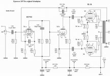
What is the cathode voltage of the first stage of the Dynavox VR70e?That's a fine example of a bad amplifier.
Do yourself a pleasure, build something else.
Mona
Dynnavox doesn't show all voltages only the power supply. Cathode will be around 0,5V.What is the cathode voltage of the first stage of the Dynavox VR70e?
Mona
Last edited by a moderator:
- Home
- Amplifiers
- Tubes / Valves
- Help and suggestions for my project based on the Radford STA-35 schematic