No, you will not burn the tweeters. You will always see that components comes in standard values. They also have tolerances like 5% or 10%. For coils you can always take a bigger value, and take of some windings to get an exact value. For capacitors you need to accept the difference or combine more capacitors in series or parallel
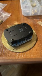
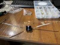
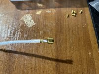
friends! I have the final stage - Assembly! look at my photos. did I solder the capacitors correctly? they didn't have a direction, so I soldered them in one direction. and look at twitter. it does not have a plus and minus sign. where should the red terminal go, and where should the black one go? and another question: should the capacitors be on the red terminal or on the black one? and, as a result, where to insert the wiring with capacitors in the Tweeter? thank you for your responses!
Attachments
-
 10E925A1-F958-488A-AFAA-93A880322009.jpeg318.2 KB · Views: 110
 -
 5167A00D-3CA6-4FE7-B27C-5B52EE55155F.jpeg348.7 KB · Views: 92
 -
 A63391E0-BE1E-4C88-9D77-77DC1FABBB5F.jpeg664.7 KB · Views: 90
 -
 6F37B38C-990E-40B4-8738-D4BE987EBF2B.jpeg516.8 KB · Views: 83
 -
 C78A1847-CFB8-40F8-8D69-74F965F0139D.jpeg703.1 KB · Views: 87
 -
 A5860F0B-7E66-438B-A68F-0BE35268D862.jpeg526.6 KB · Views: 96
I forgot to say that the calculator showed that in order to cut the tweeters at 10 kHz, I need a 1.99 uF capacitor. I didn’t find one, and took 1.5 + 0.39 + 0.1 uF.
I collected everything. but I'm afraid to turn it on. I'm waiting for your advice on connecting. how to connect the tweeter and how to connect the rat and black terminals correctly.
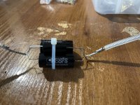
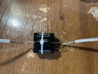
Connectors on tweeters should be different size. One trinner than the other. Capacitors are connected ok, but the legs act like antennas, bend them in towards the center, and solder the very short legs.
And you will not destroy tweeter with opposite connection, you will just have shifted the phase 180 degrees.
ok, thanks a lot for your help! it's almost two o'clock now. tomorrow I will do everything and send a photo of the finished product))
P.S. I'm afraid to make the legs of the capacitors shorter. they are too expensive now, and I want to do more experiments in the future.
P.S. I'm afraid to make the legs of the capacitors shorter. they are too expensive now, and I want to do more experiments in the future.
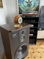
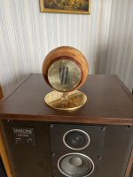
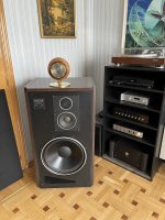
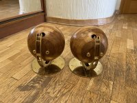
Friends, I finished them!
Thank you all for your help in creating great super tweeters! For almost a year I was fiddling with them, I got a lot of positive emotions, and I also realized that the main thing is to start and everything will work out! If it doesn't work the first time, it will work the second time.
This is the most luxurious experience. Once again, thank you all for your advice.
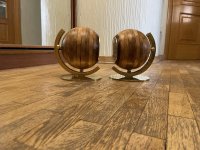
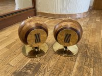
It took me about three months to develop the stand, I was trying to invent a stand that would allow these spheres to rotate. I do not pretend to be a genius, however, it seems to me that my idea, although difficult to implement, is alive. Spheres can be raised every 30 degrees. The tweeter can be directed straight, then slightly up, then 50 degrees up and then 90 degrees up so that the tweeter points up. The purpose of this is to see in which position the sound will be the coolest.
P.S. By the way, I will make another super tweeters, because there are still speakers left. 🙂
Thank you all for your help in creating great super tweeters! For almost a year I was fiddling with them, I got a lot of positive emotions, and I also realized that the main thing is to start and everything will work out! If it doesn't work the first time, it will work the second time.
This is the most luxurious experience. Once again, thank you all for your advice.
It took me about three months to develop the stand, I was trying to invent a stand that would allow these spheres to rotate. I do not pretend to be a genius, however, it seems to me that my idea, although difficult to implement, is alive. Spheres can be raised every 30 degrees. The tweeter can be directed straight, then slightly up, then 50 degrees up and then 90 degrees up so that the tweeter points up. The purpose of this is to see in which position the sound will be the coolest.
P.S. By the way, I will make another super tweeters, because there are still speakers left. 🙂
Attachments
-
 IMG_4173.JPEG721.6 KB · Views: 118
 -
 IMG_4172.JPEG660 KB · Views: 107
 -
 IMG_4171.JPEG819.7 KB · Views: 108
 -
 IMG_4170.JPEG786.1 KB · Views: 106
 -
 IMG_4166.JPEG913.5 KB · Views: 105
 -
 IMG_4165.JPEG769.2 KB · Views: 105
 -
 IMG_4164.JPEG744.7 KB · Views: 104
 -
 IMG_4163.JPEG794.7 KB · Views: 100
 -
 IMG_4162.JPEG778.7 KB · Views: 103
 -
 IMG_4161.JPEG951.1 KB · Views: 110

No need to make them shorter, just solder that way, and twist the rest.ok, thanks a lot for your help! it's almost two o'clock now. tomorrow I will do everything and send a photo of the finished product))
P.S. I'm afraid to make the legs of the capacitors shorter. they are too expensive now, and I want to do more experiments in the future.
Beautiful build Vetusto, it's like art! 👍
With regards to your capacitor leads there is No antenna effect of concern in this part of the circuit, all the speaker cables alone is a large antenna and is not a problem for a competently designed amplifier, so don't get paranoid and start twisting and bending component leads, they only become more fragile of such abuse and will break easier.
With regards to your capacitor leads there is No antenna effect of concern in this part of the circuit, all the speaker cables alone is a large antenna and is not a problem for a competently designed amplifier, so don't get paranoid and start twisting and bending component leads, they only become more fragile of such abuse and will break easier.
Speaker cables are not antennas, the pairs are normally quite close, and have no loop area. But, I agree that most amplifiers will have no issues. I dont advis to abuse the leads, just bent and solder without loop area, and gently twist the rest
Kjeldsen, there's a bit more to antenna theory than just "loops".
Also do remind, the so called "speaker cable" is a bit more than just a neatly lined up pair of ideal resistive conductors running closely along each other between the amp and speaker box, every interconnect, every crossover filter, transducer voice coils and what not either forces the conductor pair apart and/or creates loops in a complex reactive network, what are we going to do about all that, twist and bend everything together "gently"?
Don't forget that the author wants to be able to separate the capacitors from each other easily, so even twisting gently will create more problem than necessary, the creeping effect from solderig will cause most of the leads becoming quickly soldered together when the leads are close to each other, and hence much more difficult to separate requiring more unnecessary physical force to separate the leads, and add to that we don't know everyone's soldering skills.
Also do remind, the so called "speaker cable" is a bit more than just a neatly lined up pair of ideal resistive conductors running closely along each other between the amp and speaker box, every interconnect, every crossover filter, transducer voice coils and what not either forces the conductor pair apart and/or creates loops in a complex reactive network, what are we going to do about all that, twist and bend everything together "gently"?
:)Don't forget that the author wants to be able to separate the capacitors from each other easily, so even twisting gently will create more problem than necessary, the creeping effect from solderig will cause most of the leads becoming quickly soldered together when the leads are close to each other, and hence much more difficult to separate requiring more unnecessary physical force to separate the leads, and add to that we don't know everyone's soldering skills.
Thanks for support!With regards to your capacitor leads there is No antenna effect of concern in this part of the circuit, all the speaker cables alone is a large antenna and is not a problem for a competently designed amplifier, so don't get paranoid and start twisting and bending component leads, they only become more fragile of such abuse and will break easier.
I directed the legs of the capacitors upward only because there is a lot of space inside the spheres in terms of volume, but there is not enough space in length. And in this state, I just put this bunch of capacitors on the bottom for now, I made the cable as short as possible, but so that it was comfortable to put these cables on the terminals and on the tweeters.
And you're right, my goal for now is just to hear how they sound. But in the future, I want to make a separate box and make a frequency switch. At 6.5 kHz (as it is written in the tweeter's passport), at 10 kHz (as it is now), at 14.5 kHz (I have a slight drop at this frequency when measuring Diatone) and at 16.5 kHz (at this frequency there is a decrease in measurements). To be able to experiment with sound.
But I plan to produce this separate box with a crossover in the distant future (maybe in a month). Now I want to enjoy the sound. Surprisingly, the detail increased by 20 percent, I began to hear more nuances.
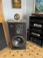
In addition, when connecting these tweeters to my acoustics, another problem was revealed: I have a very thick cable from the amplifier to the speakers, and even having bought a thin cable from the speakers to the tweeters, I could not fix them well enough in the terminals of my Diatone. I don't want to change the terminals on the Diatone speaker system. This is a complex process and will destroy the authenticity of my speakers. Therefore, I will invent a special adapter made of pure copper (or pure silver, if it is not very expensive).
I do not think that my new invention (this adapter or splitter) will be of interest to anyone. It will clearly screw (?) only in my Diatone.
I'm still euphoric that I've completed this project and it really worked. If I had a lot of money, I could start an audio design company and invite the best specialists there, and I would do the design myself. 🙂 Friends, it's such a thrill to draw something, and then participate in its manufacture. I wish everyone to start doing something with their own hands. This is amazing! 🙂
Now I want to make a speaker system. I have already created on our forum (I can already consider it ours? 🙂) a separate topic for collecting data on a stereo system. And I will do it. I have a great design idea in my head. But while I don't know what speakers I need, and how to realize the manufacture of many round cabinets, my first thought is to make them from fiberglass or carbon fiber ... But I don't know at all the technology for manufacturing parts from carbon fiber or fiberglass.
Now I want to make a speaker system. I have already created on our forum (I can already consider it ours? 🙂) a separate topic for collecting data on a stereo system. And I will do it. I have a great design idea in my head. But while I don't know what speakers I need, and how to realize the manufacture of many round cabinets, my first thought is to make them from fiberglass or carbon fiber ... But I don't know at all the technology for manufacturing parts from carbon fiber or fiberglass.
Last edited:
It was just a little help from my side, since its easy to do. I have tried radiointerference, and able to afterwards eliminate this with this very simple rule of thumb. With correct and not very advanced technique, you can always remove solder from leads before separating them.Kjeldsen, there's a bit more to antenna theory than just "loops".
Also do remind, the so called "speaker cable" is a bit more than just a neatly lined up pair of ideal resistive conductors running closely along each other between the amp and speaker box, every interconnect, every crossover filter, transducer voice coils and what not either forces the conductor pair apart and/or creates loops in a complex reactive network, what are we going to do about all that, twist and bend everything together "gently"?:)
Don't forget that the author wants to be able to separate the capacitors from each other easily, so even twisting gently will create more problem than necessary, the creeping effect from solderig will cause most of the leads becoming quickly soldered together when the leads are close to each other, and hence much more difficult to separate requiring more unnecessary physical force to separate the leads, and add to that we don't know everyone's soldering skills.
Glasfiber inspiration, in danish but mostly pictures. Its a lot of hard work.
https://www.bilgalleri.dk/fotoalbum/billeder/glasfiber-guide-trin-for-trin/17161
https://www.bilgalleri.dk/fotoalbum/billeder/glasfiber-guide-trin-for-trin/17161
Thanks for the photo! It's really difficult. But I am not afraid of difficulties. 🙂 Especially in the evenings, it's better to listen to music or mess with your favorite thing than to be stupid in front of the TV and listen to bad news.Its a lot of hard work.
Friends, good morning and good mood to you!
Once again I want to ask you for help. 🙂
I still have tweeters and a lot of wood, glue, veneer, oil and other tools, and I want to make more super tweeters. 🙂 But I was overtaken by a creative crisis. After all, I do not have any good power tools at all ... And this greatly limits my imagination in the form of a super tweeter.
The idea came to make just a cube, but to make the front part in the form of a horn ... Yes, the idea is stupid, but it seems to me that I can do it. But I lack knowledge. Do you have any links to correct horn calculations for tweeters?
Last edited:
- Home
- Loudspeakers
- Multi-Way
- how does one make a super tweeter