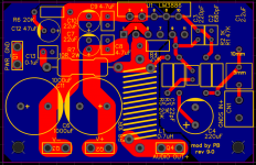
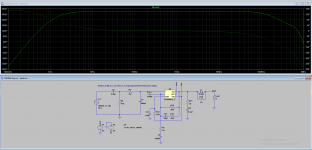
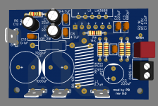
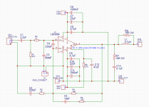
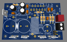
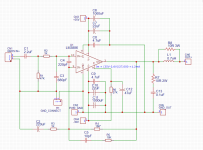
For anyone who is building amplifier with TF version of the chip and can use one screw to mount it to the heatsink, I am attaching latest 9.0 revision PCB. All values for resistors and capacitors were selected based on using LTSpice simulation. Attached also is frequency response graph screenshot.
C1 should be good quality audio grade film capacitor - WIMA, Kemet, Panasonic are good value ones.
C2, C3, C5, C8, C9 - can be ceramic C0G or X7R types.
C4 - 220uF or 330uF audio grade electrolytic cap.
C7, C10 - 22uF low ESR electrolytic caps.
C6, C11 - 1000uF generic electrolytic caps.
Gain is set to 20V/V - best overall value for wide variety of input levels.
Needs 3.3 dBu or 1.13 Vrms or 3.2 Vpp input level for the full power output into 8 ohm speakers with +-35V power supply.
L1 is DYI inductor made by wrapping wire around R8. PCB design allows for separate soldering for resistor and inductor.
Gerber files are attached. Great inexpensive site to make those PCBs is JLCPCB
Attachments
Last edited:

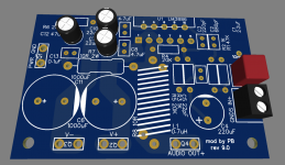
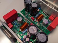
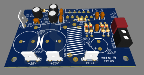
Soldered a big boy 2.2uF film cap with 47k resistor - added more red colors to the PCB lol.
Now just trying to decide on gain - probably will set it to 14V/V. That's +4dBu input line level.
I will be using this amp with Scarlet 2i4 audio interface, and max level for that is rated at 5.5dBu. That is kind of odd, because when I run the amp in simulator, feeding it 5.5dBu is right at the max level, almost clipping with the gain of 14v/v.
Attachments
They look fantastic! I will build them for sure, (I have to finde some LM3886)... thanks
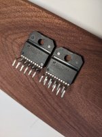
It is hard to find LM3886 anywhere in stock now. And ones in stock can be fake Chinese knock off ones.
Buying from Mouser or Digikey is the way to go. Although the wait list is about 9 month for this listing on Mouser: https://www.mouser.com/ProductDetail/Texas-Instruments/LM3886TF?qs=QbsRYf82W3EGenm0NUw7Ug==
I am attaching my chips that I know 100% original ordered from Mouser back in 2016.
Attachments

It took me a long time to figure out what kind of parts to use with the amplifier. I decided to put together a list of "ideal" parts (in my opinion) for anyone wondering about the same.
I assembled my boards with most of the film capacitors, however, C0G or X7R ceramics are a good quality substitutes. I wish I did not hurry to order all parts and waited till I knew about that. I used 330uF Panasonic OSCON in the feedback voltage divider, but hopefully that will sound good - since given other chance I would go for Nichicon or Elna audio grade electrolytics.
I also provided part numbers if you are going to order it from Mouser.
Attachments
Last edited:
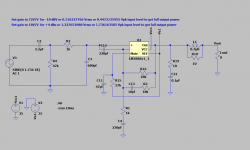
It looks that with single LM3886 and the load of 4 ohms it is best to supply it with +-28V.
On gain:
Set gain to 56V/V for -10 dBV or 0.316227766 Vrms or 0.4472135955 Vpk input level to get full output power into 8 ohm speakers (R4, R5 = 56K, C5=22pF)
Set gain to 14V/V for +4 dBu or 1.227652988 Vrms or 1.736163505 Vpk input level to get full output power into 8 ohm speakers (R4, R5 = 14K, C5=10pF)
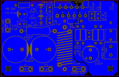
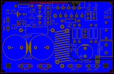
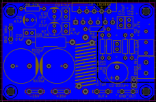
Updated layout with correct resistors sizes.
On gain:
Set gain to 56V/V for -10 dBV or 0.316227766 Vrms or 0.4472135955 Vpk input level to get full output power into 8 ohm speakers (R4, R5 = 56K, C5=22pF)
Set gain to 14V/V for +4 dBu or 1.227652988 Vrms or 1.736163505 Vpk input level to get full output power into 8 ohm speakers (R4, R5 = 14K, C5=10pF)
Updated layout with correct resistors sizes.
Attachments
Last edited:
It looks that with single LM3886 and the load of 4 ohms it is best to supply it with +-28V.
On gain:
Set gain to 56V/V for -10 dBV or 0.316227766 Vrms or 0.4472135955 Vpk input level to get full output power into 8 ohm speakers (R4, R5 = 56K, C5=22pF)
Set gain to 14V/V for +4 dBu or 1.227652988 Vrms or 1.736163505 Vpk input level to get full output power into 8 ohm speakers (R4, R5 = 14K, C5=10pF)
Updated layout with correct resistors sizes.
Correction:
for R4, R5 = 56K, C5 should be 10pF
and for R4, R5 = 14K, C5 should be 22pF
Great cases for DIY projects - https://chevalstore.com/product-category/sa-series/
I just got mine in the mail and it looks really good quality.
I just got mine in the mail and it looks really good quality.
Where do you have the Kicad-files PCB-mount flat-connectors from? (incl. 3D-model)
Can you share them or their source?
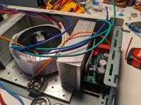
Those aluminium bars you´re using to push the chip against the heatsink look awfully bent.
Hope you didn´t apply that much pressure to get them to this shape!
Pushing against the edges of the PLASTIC package might break it otherwise.
You hardly need more pressure than one can easily apply with their thumb pressing against the chip.
Ideally that pressure is applied evenly over the whole surface of the chip with a flat bar or so.
Can you share them or their source?
Those aluminium bars you´re using to push the chip against the heatsink look awfully bent.
Hope you didn´t apply that much pressure to get them to this shape!
Pushing against the edges of the PLASTIC package might break it otherwise.
You hardly need more pressure than one can easily apply with their thumb pressing against the chip.
Ideally that pressure is applied evenly over the whole surface of the chip with a flat bar or so.
Where do you have the Kicad-files PCB-mount flat-connectors from? (incl. 3D-model)
Can you share them or their source?
Those aluminium bars you´re using to push the chip against the heatsink look awfully bent.
Hope you didn´t apply that much pressure to get them to this shape!
Pushing against the edges of the PLASTIC package might break it otherwise.
You hardly need more pressure than one can easily apply with their thumb pressing against the chip.
Ideally that pressure is applied evenly over the whole surface of the chip with a flat bar or so.
Those are made from aluminum and bend pretty easy with very little pressure applied. I should've drilled holes closer to the chip.
I used easyeda for 3d model. I'll look it up later for you.
Where do you have the Kicad-files PCB-mount flat-connectors from? (incl. 3D-model)
Can you share them or their source?
You can find those in easyEDA if you search for CONN-TH_726386-2 footprint
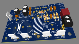
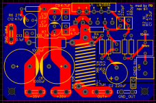
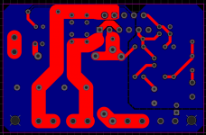
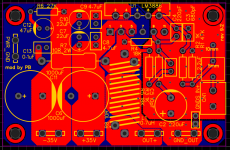
In this revision fixed ground layout.
It is critical for this version for the load to be 8 ohms
Power is +-35V DC
Input level is set to be +4 dBU
Output power should be 50W into 8 ohm speakers.
It is critical for this version for the load to be 8 ohms
Power is +-35V DC
Input level is set to be +4 dBU
Output power should be 50W into 8 ohm speakers.
Attachments

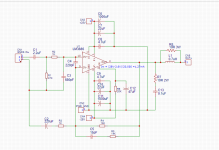
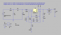
Attached are schematics for different input line levels:
+4 dBU
-10 dBV
Those are for +-35V power supply and 8 ohm load resistance.
Gain is set to 18 or 72 by changing feedback resistors to 18k or 71.5K respectively.
Johnson noise is higher for 71.5K resistor.
It is -106 dBV or -103.78 dBU, calculated over the range of 20KHz, with temperature of 40 degrees Celsius.
For 18K resistor it is -112 dBV or -109.78 dBU, same freq range and temp.
Attachments
Last edited:
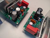
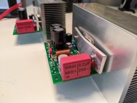
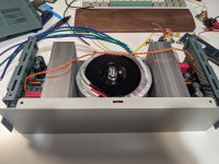
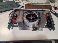
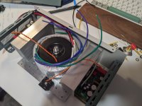
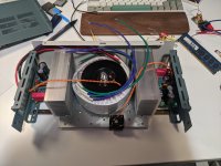
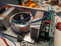
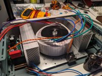
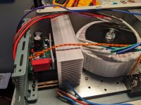
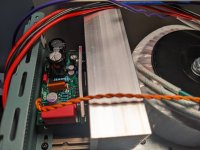
Made some progress on the build today.
Case is little too tight, but on the other hand it takes little footprint on my table, so that's good.
Got AnTek AS-2222 200VA 22V transformer that came in the mail today. Attaching it to the case was a challenge. I was able to attach it by using a piece of metal that I got from Lowes in the wood framing department - it is a bracket that is used to tie down wood studs together. Looks nice and it added extra rigidity to the case.
Case that I used is Cheval SACN2.0D1W2 - it is 2U high. Size is 87 x 178 x 305 mm. It came with two mount bars that are attached at the bottom and have rail space inside of them to slide in small nuts. I attached framing bracket to those with 6 screws.
Heatsinks were drilled and attached to framing bracket too. Used Awxlumv Large Aluminum Heatsink 4.72" x2.71" x 1.41" / 120 x 69 x 36mm that I got from Amazon.
Attachments
-
 PXL_20220503_000751902.jpg339.9 KB · Views: 134
 -
 PXL_20220503_000731758.jpg388.9 KB · Views: 128
 -
 PXL_20220503_000728338.jpg355.8 KB · Views: 127
 -
 PXL_20220503_000722834.jpg389.3 KB · Views: 132
 -
 PXL_20220503_013950797.jpg433.3 KB · Views: 137
 -
 PXL_20220503_013948374.jpg499.1 KB · Views: 113
 -
 PXL_20220503_013940499.jpg488.4 KB · Views: 119
 -
 PXL_20220503_013934585.jpg436.7 KB · Views: 128
 -
 PXL_20220503_013927300.jpg361.3 KB · Views: 139
Last edited:
Yes, maybe in the future when I have timeVery Cool project, have you ever think doing something similar with TDA7294 instead?
Offcourse, I was just courious.Yes, maybe in the future when I have time
Cheers
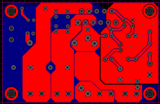
Another revision of the simple gainclone chipamp PCB!
In this revision improved ground plains, added mounting holes on the side of the heatsink, + and - traces are pours now.
In this revision improved ground plains, added mounting holes on the side of the heatsink, + and - traces are pours now.
Attachments
- Home
- Amplifiers
- Chip Amps
- Yet another LM3886 gainclone PCB based on circuitbasics.com