I repaired a channel in this amp using T03P outputs ( 2SA2223a & 2SC6145A) and replaced the blown drivers with Toshiba TTA004B & TTC004B.
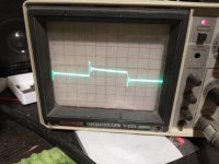
Its up and running, but I'm getting oscillations looking at a square wave at 10kHz .
I tried adding 47pf caps to the drivers with no luck... Should I be adding some caps to the outputs as well??
Its up and running, but I'm getting oscillations looking at a square wave at 10kHz .
I tried adding 47pf caps to the drivers with no luck... Should I be adding some caps to the outputs as well??
Attachments
Last edited:
I should add, I replaced Q 4&5 and Q 11&12 with KSC 3503/ A1381.I repaired a channel in this amp using T03P outputs ( 2SA2223a & 2SC6145A) and replaced the blown drivers with Toshiba TTA004B & TTC004B.
Its up and running, but I'm getting oscillations looking at a square wave at 10mhz .
I tried adding 47pf caps to the drivers with no luck... Should I be adding some caps to the outputs as well??
Oh .. jeez, sorry it was 10 kHz... I fixed itWhat is "mhz"? milliHertz? MegaHertz?
Sometimes, replacing Original transistors with a modern equivalent causes ringing, due to the higher ability of new transistors, and yes, a cap on one side of an output from base to collector can stem ringing.
Does it matter which side? NPN??Sometimes, replacing Original transistors with a modern equivalent causes ringing, due to the higher ability of new transistors, and yes, a cap on one side of an output from base to collector can stem ringing.
Trial and error - I don't know the schematic involved.Does it matter which side? NPN??

Thanks!Trial and error - I don't know the schematic involved.
There actually is no schematic for this? It is very similar to an AU-X1 I've readThanks!
I have simulated au-x1 not the x11 but I think they maybe similar designs. I think the compensation network needs some slight increase in capacitance to settle down the ringing. Iirc there was a case on Audiokarma where we worked out a solution, it was in the Sansui section
Well.. I was going to try adding a little extra at the base collectors of outputs, just waiting on parts. Anyone have an educated guess how much I should try? I ordered 10pf , 33 pf, and 47 pf C0G's
Its in the VAS that you require extra compensation,
if I refer to AU-X1 schematic, it would be adding starting from 10+pF increasing as required for stability and the 10Khz square wave test,
add across C09,C10 (3p) the b-c of Tr10,11, which form the push-pull VoltageAmpStage.
if I refer to AU-X1 schematic, it would be adding starting from 10+pF increasing as required for stability and the 10Khz square wave test,
add across C09,C10 (3p) the b-c of Tr10,11, which form the push-pull VoltageAmpStage.
Nice. Thanks, very helpful!!Its in the VAS that you require extra compensation,
if I refer to AU-X1 schematic, it would be adding starting from 10+pF increasing as required for stability and the 10Khz square wave test,
add across C09,C10 (3p) the b-c of Tr10,11, which form the push-pull VoltageAmpStage.
I replaced these transistors on this channel with the a1381/c3503 , could this be part of the issue?
Last edited:
I notice that the c3503/a1381 have a very low Cob? I also have ksc2690ay and ksa1220 on hand? Worth a try?I have simulated au-x1 not the x11 but I think they maybe similar designs. I think the compensation network needs some slight increase in capacitance to settle down the ringing. Iirc there was a case on Audiokarma where we worked out a solution, it was in the Sansui section
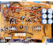
Here is an instance where "new" transistors were replaced due to "original" ones were not available.
Notice the highlighted notes and parts.
This can apply to other amps at times.

Notice the highlighted notes and parts.
This can apply to other amps at times.
I got the overshoot tamed down , but still have some ringing... What is the method to test for stability?
- Home
- Amplifiers
- Solid State
- Sansui AU-X11 oscillation