Sadly many fakes around.
I was burnt with a lot of supposedly ST TDA2050, "perfect" in every detail, such as yours, bought from a supposedly "serious" supplier 😱 which can NOT stand +/-22V (so 44V end to end) rails at all.
Some start overheating on their own, some wait until passing some signal through, fact is they are all unusable.
But they all work perfectly well, zero problems, with +/-18V (hint hint) so I guess they are relabelled TDA 2030 chips.
A problem for me because I had designed 25/30W Guitar amps, for which there is a market; not interested at all in 15W ones of which the market is more than saturated.
Just not to fully waste them, I´ll probably design a new bridged output using two of them, for real solid 30W RMS, but for now that is in the back burner, lots of unfinished projects before them.
EDIT: I suggest you build a quick and dirty 16+16V supply, using a 12+12V AC transformer, or even a voltage doubler one out of a single 12VAC winding just to test your "TDA 2050". IF they now work properly, then you got the same kind of fakes as I did: relabelled TDA2030 which is the most common out there.
When you say +\- 18volt . You mean +18/-18 or +9/-9 volt , I confusedSadly many fakes around.
I was burnt with a lot of supposedly ST TDA2050, "perfect" in every detail, such as yours, bought from a supposedly "serious" supplier 😱 which can NOT stand +/-22V (so 44V end to end) rails at all.
Some start overheating on their own, some wait until passing some signal through, fact is they are all unusable.
But they all work perfectly well, zero problems, with +/-18V (hint hint) so I guess they are relabelled TDA 2030 chips.
A problem for me because I had designed 25/30W Guitar amps, for which there is a market; not interested at all in 15W ones of which the market is more than saturated.
Just not to fully waste them, I´ll probably design a new bridged output using two of them, for real solid 30W RMS, but for now that is in the back burner, lots of unfinished projects before them.
EDIT: I suggest you build a quick and dirty 16+16V supply, using a 12+12V AC transformer, or even a voltage doubler one out of a single 12VAC winding just to test your "TDA 2050". IF they now work properly, then you got the same kind of fakes as I did: relabelled TDA2030 which is the most common out there.
Oh, I suggested 12+12VAC or even a single 12VAC transformer because it´s a VERY popular/common value and "everybody has one" 🙂Very very nice post my friend …. I'm probably going to do that with 2030 ,, sounds good 👍.. but I don’t have now a 12-0-12 vac transformer ….. do you have a good schematic for the 2030 ? And can I test it with -15/+15 vdc ?
And it happens to give you +/-16V , perfect for this test.
I suggested +/-18V so 36V end to end (from + rail to -rail) because that´s the maximum allowed TDA2030 and at least on the fakes I used, works very well.
Value straight from the datasheet:
https://pdf1.alldatasheet.es/datasheet-pdf/view/25043/STMICROELECTRONICS/TDA2030.html
I mean +18VDC/-18VDC but that is usually written as +/-18VWhen you say +\- 18volt . You mean +18/-18 or +9/-9 volt , I confused
Use the schematic you have, "they are all the same", just with increasingly better specs.do you have a good schematic for the 2030 ?
So use your TDA2050 schematic, just "feed it as if it were a TDA2030" specially because it probably is 🙁
In a nutshell. use the amp you built and the suspect TDA2050 you bought, just feed it */-18V or less.
So get a 12+12VAC transformer, 1A (just enough) or 1.5A which will work relaxed and use your current power supply.
You are closer than you think to a properly working Guitar Amp, only slightly less power than expected.
No big deal and still more than enough to annoy Neighbours and Family 😉
More important: what speaker will you use? If possible, a "Guitar" one.
Different to cables, capacitors, etc. , in Guitar speakers each one has its own "voice"

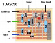
to my surprise I found a forgotten i.c. in my drawer which reads TSL tda2040V. it is definitely not genuine. but I tried it and it worked. I fed it with - \ + 15vdc but it sounded very low and it was quite distorted .. anyway I will try with a genuine 2030 today, I also found this layout that is used for guitar with 2030 ..for speaker I have 3x12” celestion ( 2 on cabinet and one on my big Marshall mg100dfx …I'm tired this week with the power amp section and I want to finish it.Oh, I suggested 12+12VAC or even a single 12VAC transformer because it´s a VERY popular/common value and "everybody has one" 🙂
And it happens to give you +/-16V , perfect for this test.
I suggested +/-18V so 36V end to end (from + rail to -rail) because that´s the maximum allowed TDA2030 and at least on the fakes I used, works very well.
Value straight from the datasheet:
https://pdf1.alldatasheet.es/datasheet-pdf/view/25043/STMICROELECTRONICS/TDA2030.html
I mean +18VDC/-18VDC but that is usually written as +/-18V
Use the schematic you have, "they are all the same", just with increasingly better specs.
So use your TDA2050 schematic, just "feed it as if it were a TDA2030" specially because it probably is 🙁
In a nutshell. use the amp you built and the suspect TDA2050 you bought, just feed it */-18V or less.
So get a 12+12VAC transformer, 1A (just enough) or 1.5A which will work relaxed and use your current power supply.
You are closer than you think to a properly working Guitar Amp, only slightly less power than expected.
No big deal and still more than enough to annoy Neighbours and Family 😉
More important: what speaker will you use? If possible, a "Guitar" one.
Different to cables, capacitors, etc. , in Guitar speakers each one has its own "voice"
The layout is from here
Attachments
How do you know?to my surprise I found a forgotten i.c. in my drawer which reads TSL tda2040V. it is definitely not genuine.
If bought long ago, it might be a good one.
I fed it with - \ + 15vdc but it sounded very low and it was quite distorted
What supply did you use?
A +/-15V one meant for a preamp , or a couple Op Amps, can NOT feed a Power Amp driving a speaker.
😱 😱 😱 LOTS|of alarms are sounding and red flags rising:for speaker I have 3x12” celestion ( 2 on cabinet and one on my big Marshall mg100dfx
- Describe each of those speakers, specially impedance-
- describe wiring.
You can´t happily connect every speaker in the house to that poor TDA20xx, maybe that was the problem from Day 1
Suspect the speaker in MG100 is 4 ohm but measure all 3 and draw wiring.
The layout is from here
Why?
Use the one made for the Orange 20W with a 2050, same pinout and components.
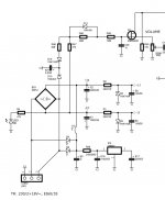
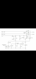
First of all . For power amp I use ( alone ) -+\15vdc . For the other parts I use 9volt batt , are separate . Second I make test to hear some difference between those circuits .. maybe at the last I will use the orange circuit .. and speakers is 4 ohms , the one of Marshall is 4ohm , the other 2 on cabinet are 8ohm each , on parallel wiring … now I’m thinking to instead buy a 12-0-12 vac transformer , I will use the 15-0-15 vac ( that’s I have ) with i.c. 7818 and i.c. 7918 to feed the power amp … and something else .. here is the the schematic of 2 different voltages ( 2 positive and 2 negative ) , I will use the +-/22vdc with 18volt regulator for power amp section and the +-/15vdc for preamp section , will there be a problem? or should they be separate transformers? By the way thanx for your answers , and your patience with me,, you are great 👍How do you know?
If bought long ago, it might be a good one.
What supply did you use?
A +/-15V one meant for a preamp , or a couple Op Amps, can NOT feed a Power Amp driving a speaker.
😱 😱 😱 LOTS|of alarms are sounding and red flags rising:
- Describe each of those speakers, specially impedance-
- describe wiring.
You can´t happily connect every speaker in the house to that poor TDA20xx, maybe that was the problem from Day 1
Suspect the speaker in MG100 is 4 ohm but measure all 3 and draw wiring.
Why?
Use the one made for the Orange 20W with a 2050, same pinout and components.
Attachments

Ouch!!! What I imagined/sort of expected. 😳

That supply CAN NOT feed a power amp, only a Preamp.
It´s HEAVILY current limited: (22-15)V/330 ohm=21 milli Amperes while you need an about 1 full Ampere (1000 milli Ampere) supply.
No surprise no TDA20xx works there.
You need a 12+12VAC 1 Ampere (or 24 VoltAmpere (VA), same thing) or better to get "good" +/-16V with enough current capability to feed your amplifier.
Do you use a single 9V batt or two to get +/-9V?
Forget regulators in power amps, only 0.01% of amps out there use regulators, just get the proper transformer.
As of helping you, don´t worry.
Don´t get much, if at all, in other areas, unless basic principles or Physics are grossly disregarded, but MI amps are "my thing" 😉
Since 1969, go figure. 😱
First of all . For power amp I use ( alone ) -+\15vdc .
That supply CAN NOT feed a power amp, only a Preamp.
It´s HEAVILY current limited: (22-15)V/330 ohm=21 milli Amperes while you need an about 1 full Ampere (1000 milli Ampere) supply.
No surprise no TDA20xx works there.
You need a 12+12VAC 1 Ampere (or 24 VoltAmpere (VA), same thing) or better to get "good" +/-16V with enough current capability to feed your amplifier.
Please show the preamp you are using.For the other parts I use 9volt batt , are separate .
Do you use a single 9V batt or two to get +/-9V?
Again what I imagined: if you wire all 3 speakers in parallel, you will get a total 2 ohm load .... your chipamp will NOT be happy with that.Second I make test to hear some difference between those circuits .. maybe at the last I will use the orange circuit .. and speakers is 4 ohms , the one of Marshall is 4ohm , the other 2 on cabinet are 8ohm each , on parallel wiring
No.… now I’m thinking to instead(of?) buy a 12-0-12 vac transformer , I will use the 15-0-15 vac ( that’s I have ) with i.c. 7818 and i.c. 7918 to feed the power amp
Forget regulators in power amps, only 0.01% of amps out there use regulators, just get the proper transformer.
No regulators for power amps.and something else .. here is the the schematic of 2 different voltages ( 2 positive and 2 negative ) , I will use the +-/22vdc with 18volt regulator for power amp section
Fine, but please show your preamp schematic to be certain.and the +-/15vdc for preamp section
As of helping you, don´t worry.
Don´t get much, if at all, in other areas, unless basic principles or Physics are grossly disregarded, but MI amps are "my thing" 😉
Since 1969, go figure. 😱
Don’t worry for the speakers it’s 4 ohms output… basically it’s 2 cabinets , 1 with 2 speakers and 1 with 1 speaker . : ) .now the power schematic is from the orange schematic …. So with zeners -+\15volts I can’t use for power ? Only for preamp ?Ouch!!! What I imagined/sort of expected. 😳
That supply CAN NOT feed a power amp, only a Preamp.
It´s HEAVILY current limited: (22-15)V/330 ohm=21 milli Amperes while you need an about 1 full Ampere (1000 milli Ampere) supply.
No surprise no TDA20xx works there.
You need a 12+12VAC 1 Ampere (or 24 VoltAmpere (VA), same thing) or better to get "good" +/-16V with enough current capability to feed your amplifier.
Please show the preamp you are using.
Do you use a single 9V batt or two to get +/-9V?
Again what I imagined: if you wire all 3 speakers in parallel, you will get a total 2 ohm load .... your chipamp will NOT be happy with that.
No.
Forget regulators in power amps, only 0.01% of amps out there use regulators, just get the proper transformer.
No regulators for power amps.
Fine, but please show your preamp schematic to be certain.
As of helping you, don´t worry.
Don´t get much, if at all, in other areas, unless basic principles or Physics are grossly disregarded, but MI amps are "my thing" 😉
Since 1969, go figure. 😱
Attachments
First of all , I understand , that schematic for both power of the circuit is fail ,,, now , I don’t wiring 3 speakers just 1 or 2 and the output is 4 ohm … I test the 2030 with 18 volt regulator and work great ,,,but I have a slight hum and the heat sink is slightly hot …. And I try to test with 12 voltage regulator , and guess ! It work perfect without hums and temperatures and nothing ,,,, so I listen you and I use the first circuit of ORANGE with 2050 ( with 12-0-12 vac transformer , and this trans give voltage only on the power amp section ) and I put an onother 9-0-9 vac with 9 volt regulator to feed the clean preamp and the gain preamp section … right ?
Yes.
Power amp needs transformer >diodes >capacitors > power amp.
Nothing in between.
Can´t answer for your preamp because I never saw a schematic 😉
Power amp needs transformer >diodes >capacitors > power amp.
Nothing in between.
Can´t answer for your preamp because I never saw a schematic 😉
Here is the schem 🙂Yes.
Power amp needs transformer >diodes >capacitors > power amp.
Nothing in between.
Can´t answer for your preamp because I never saw a schematic 😉
Attachments

Thanks.
Your preamp needs +/-15V which your power supply can offer, of course.
Not sure how you are powering it from a single +9V battery.
And even if using two as a split power supply, what for? The original power supply is already offering the proper +/-15V
Your preamp needs +/-15V which your power supply can offer, of course.
Not sure how you are powering it from a single +9V battery.
And even if using two as a split power supply, what for? The original power supply is already offering the proper +/-15V
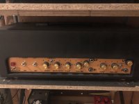
The problem is , when I connect the +-/15 volts on preamp ,, it doesn’t work ,,, make a strange hum and the signal doesn’t pass …but I have to tell you the circuit with 2030 with +-/12vdc it’s awesome !! Nice clean sound with good volume for room use ..btw… my options ( because I’m tired with this preamp ) . .. I keep the power amp with tda 2050..and I add at the input of amp the “maxon ts 808” as preamp and a 3band EQ like “tone job” from earthquakes devices ,,, and between of 2 , I add a mxr distortion plus .. I’m testing now and the sound it’s GREAT !.. by the way just show you my 2 tubes amplifiers .. the one is a clone of Marshall 1974x 18watt and the other is clone of jcm800 50watt .. 🤟🏻Thanks.
Your preamp needs +/-15V which your power supply can offer, of course.
Not sure how you are powering it from a single +9V battery.
And even if using two as a split power supply, what for? The original power supply is already offering the proper +/-15V
Attachments
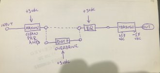
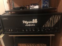
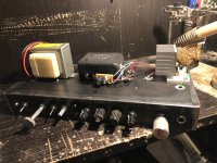
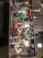
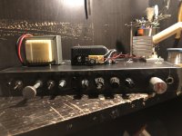
Hello to everyone.. I had a lot of work and I did not deal with my project .. but now I am finishing it little by little now .. I am very happy because it works exactly as I want and without technical problems .. the recipe worked with the entry to enter a clean preamp - (parallel with mxr dist +) and to continue in opamp EQ .. and all this to list in 2050 tda (i dont found the original of ST, but its pretty nice) and the circuit of EQ kepps the MASTER volume… now I’m trying to make the puff speaker startup , because when I open it make the speaker a PUFF sound ( I don’t know how to explain this but I’m sure you understand it ) and when I’m finish and this section , I finish the chassis ( Color - extra upper chassis ) ….
Attachments
Someone give he’s idea for this
https://www.diyaudio.com/community/threads/style-jcm800-diode-clipping.385605/
https://www.diyaudio.com/community/threads/style-jcm800-diode-clipping.385605/
I will suggest you to go for tda2003 or tda2002 . Because they are not too popular you can find them genuine
- Home
- Amplifiers
- Solid State
- Explain strange solid state schematic