It will probably be OK without a resistor so just connect the speaker directly. Genuine TDA2050 chips are 4 ohm rated.
Nice …. Thank youuuuuIt will probably be OK without a resistor so just connect the speaker directly. Genuine TDA2050 chips are 4 ohm rated.
Schematics like that one are a lot of times over-designed by someone obsessed with complexity.This schematic is flawed . Its too complicated . Theres really nothing in it . Rectifier is rectifying tda2050 is amplifing . Preamp is preamplifing . Thats it . Why you want the working can you explain what are your end goal .
In other words, a nervous nutcase with time on their hands and a mind that obsesses over stuff.

I make some changes on the preamp and the power amp breadboard … and the sound it’s awesome …I put it on my 2x 12” celestion cab and the loudness It’s pretty good… by the way , the transformer that I work for this circuit , 12 vac … and it’s work perfect ,, thanx everybody for the help .. king regards from Athens / Greece
Remember Designers on a salary (as opposed to one time hired Consultants) must "justify" it, so now and then must add "something" to perfectly good and working circuits.Schematics like that one are a lot of times over-designed by someone obsessed with complexity.
In other words, a nervous nutcase with time on their hands and a mind that obsesses over stuff.
At least, that´s the only explanation I find to many unnecessary if not useless "mods" and "tweaks" I often find.
Me? I regularly leave designs untouched for years if working fine and parts still easily available.
FWIW I never cared to add start mute to avoid turn-on thump, nor turn OFF one to avoid Op Amp "squeal" , simply improved grounding array until it no longer appeared.
Solving a problem is better than hiding it 😉
I've added a time-delay to 'some' amp outputs to avoid heavy thumps at turn-on.Remember Designers on a salary (as opposed to one time hired Consultants) must "justify" it, so now and then must add "something" to perfectly good and working circuits.
At least, that´s the only explanation I find to many unnecessary if not useless "mods" and "tweaks" I often find.
Me? I regularly leave designs untouched for years if working fine and parts still easily available.
FWIW I never cared to add start mute to avoid turn-on thump, nor turn OFF one to avoid Op Amp "squeal" , simply improved grounding array until it no longer appeared.
Solving a problem is better than hiding it 😉
Other amps, like cap-coupled, aren't too annoying, only to those that are annoyed by that split-second noise that usually obsessed nervous nutty people are bothered by.
And that's their problem, not mine.
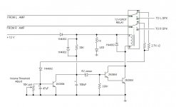
My design of an optional delay is very simple, on a perfboard or pc board 2"x3" takes up the space of a pack of cigarettes, so it can be mounted anywhere appropriate.
And, additionally, it has a volume sensor, which, if the amp was last used at high volume, it will not allow the speakers to connect until the volume is lowered to a preset reasonable level.
This is to eliminate the sudden blast that would happen if say, someone was sleeping nearby, or a child cranked up the volume knob when the amp was turned off.
Also, is used in a cap-coupled amp, it allows the output cap to 'charge up' to the half-voltage level prior to connecting the speakers, and avoids that thump.
Other than that, I just like to keep things simple.
Attachments
Last edited:
only to those that are annoyed by that split-second noise that usually obsessed nervous nutty people are bothered by.
And that's their problem, not mine.
Well it depends how seriously you take the design I guess. To me an amp should be silent at power on and power off and also not be fazed by rapid on/off switching either. Any visual indicators or panel lighting should not be affected by rail variations (unintended sound to light as we often used to see on cheapo systems as you whack the volume up) and I also like any LED's to promptly go out on power off and not fade into the distance as supplies discharge.
All are only small points but greatly enhance the 'feel' of a product.
Well Mooly, I certainly won't disagree with your comment there.Well it depends how seriously you take the design I guess. To me an amp should be silent at power on and power off and also not be fazed by rapid on/off switching either. Any visual indicators or panel lighting should not be affected by rail variations (unintended sound to light as we often used to see on cheapo systems as you whack the volume up) and I also like any LED's to promptly go out on power off and not fade into the distance as supplies discharge.
All are only small points but greatly enhance the 'feel' of a product.
A nicely operating piece of equipment can enhance its quality.
My simple circuit (above) works nicely, and has a quick reset time in case the power is turned off and then back on.
The only noise from it is the relay click.
The on-board LED is there to quickly discharge/reset the timing circuit at power-off.
The diode across the 33K resistor helps with that discharge.
With the values listed, the delay is around 5 seconds, adjustable by changing the 100uf cap.
Thanks 🙂Well Mooly, I certainly won't disagree with your comment there.
A nicely operating piece of equipment can enhance its quality.
It's all the little details taken together that can make something a joy to use I find. Your circuit is fine and I like the auto detect of a volume level that is way to high... nice feature. The Zener that allows a decent voltage to develop across the cap is worthwhile to and something that's often omitted.
Yes, part of the timing is the zener's knee 'kick-in' voltage.Thanks 🙂
It's all the little details taken together that can make something a joy to use I find. Your circuit is fine and I like the auto detect of a volume level that is way to high... nice feature. The Zener that allows a decent voltage to develop across the cap is worthwhile to and something that's often omitted.
Works like a charm.
So guys I have now a very strange problem ,, I finish the voltage board -clean preamp board - overdrive board and power amp board … I test the clean preamp with power amp and the sound is great … now I test the overdrive board with power amp and I have some kind of oscillation … I test again the O.D. Board on my Marshall amp and works perfect without oscillation .. and I test an onother overdrive pedal with the power amp board and work perfect without oscillation … note : the O.D. Board works with 9vdc instead of 15vdc of preamp …. Where is the f***** problem !?!?!?! Any idea ?
I think we would need to see all the circuit details. Could you be driving the power amp into some sort of clipping so it is latching up and appearing to oscillate?
I put my very very high distortion pedal in frond of power amp and I dial the master volume all the way up .. power amp works great ,, but I can’t understand what is going on with the other O.D. Board ,,, I don’t have time to find it ,, just I add onother board for o.d… thanx by the way ..I think we would need to see all the circuit details. Could you be driving the power amp into some sort of clipping so it is latching up and appearing to oscillate?
Yes.So guys I have now a very strange problem ,, I finish the voltage board -clean preamp board - overdrive board and power amp board … I test the clean preamp with power amp and the sound is great … now I test the overdrive board with power amp and I have some kind of oscillation … I test again the O.D. Board on my Marshall amp and works perfect without oscillation .. and I test an onother overdrive pedal with the power amp board and work perfect without oscillation … note : the O.D. Board works with 9vdc instead of 15vdc of preamp …. Where is the f***** problem !?!?!?! Any idea ?
The OD board has way more gain than the clean/normal one, so grounding and layout become WAY more critical.
The original one, your OD pedal, etc. , have already spent some time debugging that.
Sometimes it takes 1 year from "basic idea drawn on a napkin" to a real product made and sold commercially.
You will see that even products sold commercially and in large amounts, are still being revised and perfected, new versions appear, just look at the schematics.
Typically you will find at the bottom right of the schematic, where model and designer appear, there is a small box showing revisions and what was changed, sometimes seemingly unimportant part values.
Also official service shops regularly receive Factory update revisions to be applied to amps (or other products) which reach the shop.
I congratulate you on having built a working copy, now at your own pace you can tweak small details such as this .
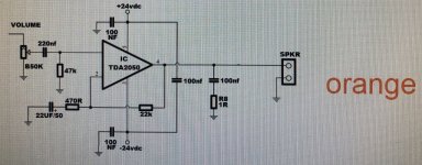
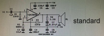
I found the problem ,,,, it’s the power amp , the tda2050 is dead or working like zombie .. I put onother new 2050 and I notice the heat sink is burning !!! I test it with clean signal and for 5-6 minutes is ok , but starting to make strange noises and the guitars clean signal distorted ,, and now just make a hum noise .. I am using the schematic of ORANGE for tda2050 … and I show you the original schematic of tda …
Attachments
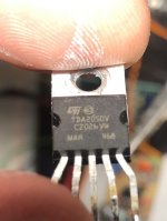
Sadly many fakes around.
I was burnt with a lot of supposedly ST TDA2050, "perfect" in every detail, such as yours, bought from a supposedly "serious" supplier 😱 which can NOT stand +/-22V (so 44V end to end) rails at all.
Some start overheating on their own, some wait until passing some signal through, fact is they are all unusable.
But they all work perfectly well, zero problems, with +/-18V (hint hint) so I guess they are relabelled TDA 2030 chips.
A problem for me because I had designed 25/30W Guitar amps, for which there is a market; not interested at all in 15W ones of which the market is more than saturated.
Just not to fully waste them, I´ll probably design a new bridged output using two of them, for real solid 30W RMS, but for now that is in the back burner, lots of unfinished projects before them.
EDIT: I suggest you build a quick and dirty 16+16V supply, using a 12+12V AC transformer, or even a voltage doubler one out of a single 12VAC winding just to test your "TDA 2050". IF they now work properly, then you got the same kind of fakes as I did: relabelled TDA2030 which is the most common out there.
Last edited:
Very very nice post my friend …. I'm probably going to do that with 2030 ,, sounds good 👍.. but I don’t have now a 12-0-12 vac transformer ….. do you have a good schematic for the 2030 ? And can I test it with -15/+15 vdc ?Sadly many fakes around.
I was burnt with a lot of supposedly ST TDA2050, "perfect" in every detail, such as yours, bought from a supposedly "serious" supplier 😱 which can NOT stand +/-22V (so 44V end to end) rails at all.
Some start overheating on their own, some wait until passing some signal through, fact is they are all unusable.
But they all work perfectly well, zero problems, with +/-18V (hint hint) so I guess they are relabelled TDA 2030 chips.
A problem for me because I had designed 25/30W Guitar amps, for which there is a market; not interested at all in 15W ones of which the market is more than saturated.
Just not to fully waste them, I´ll probably design a new bridged output using two of them, for real solid 30W RMS, but for now that is in the back burner, lots of unfinished projects before them.
EDIT: I suggest you build a quick and dirty 16+16V supply, using a 12+12V AC transformer, or even a voltage doubler one out of a single 12VAC winding just to test your "TDA 2050". IF they now work properly, then you got the same kind of fakes as I did: relabelled TDA2030 which is the most common out there.
- Home
- Amplifiers
- Solid State
- Explain strange solid state schematic