Hello everyone!
I am looking to create a simple speaker protection board for my diy project. I will be having two LM3886 in parallel with the DC offset regulated by servo. My concern is that on power on - DC will swing between +-35V power supply for the speaker output. I want to remedy that by using a simple time delay circuit that will drive tow Mosfet based relays.
I have +-15V that will be used to power the time delay circuit.
Any input and help will be greatly appreciated!
Here is what I have so far:

Have a look at a thread called "output relays". It is full of information about SSR and speaker protection.
I believe bonsai, xrk and others made speaker protection boards/circuits that you can study.
I built the circuit in above thread from pma in post 288 but there are many other solutions.
(If you want the kicad files for it, let me know. I might even have pcbs left)
You will also find solutions how to substitute relais with SSR including gerber files from prasi and others.
Like this?All the LEDs, even inside the TLP parts, need resistors. Or run them all in series.
simple, but too simple?
what about dc detection and fast turn off?
Way over my head to design something like that. I can find stand alone schematics for fast turn off, or DC detect, or time delay but blending them all together is a big unknown for me.
Found this post - https://www.diyaudio.com/community/threads/simple-universal-speaker-delay-using-a-triac.224957/
Combines time delay with fast turn off.
Drafted it in LTspice, but I'm new to it so probably a few mistakes were made....
Combines time delay with fast turn off.
Drafted it in LTspice, but I'm new to it so probably a few mistakes were made....
Attachments
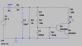
I am trying to work out how you are actually turning those FETS on - you need a decent Vgs...
Or did I miss something really fundamental here.
There are an awful lot of simple and effective designs out there using relays. They work, and are commonly used for very good reason.
I do suggest that you look at some of them, as you need no more than a handful of transistors and a relay to do time delay and DC protect. And I have a creeping feeling that those FETs wont do what you want without something a little more complex than you have there.
I am trying to work out how you are actually turning those FETS on - you need a decent Vgs...
Or did I miss something really fundamental here.
There are an awful lot of simple and effective designs out there using relays. They work, and are commonly used for very good reason.
I do suggest that you look at some of them, as you need no more than a handful of transistors and a relay to do time delay and DC protect. And I have a creeping feeling that those FETs wont do what you want without something a little more complex than you have there.
I think it is 9V that comes out from optocoupler that opens those mosfets
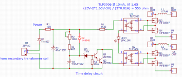
So I've made mistake calculating resistor - for LEDs in series voltages added, but current stays the same. Based on that (23V - 6V)* 0.01A = 1700 ohm
Ok, I bite...I think it is 9V that comes out from optocoupler that opens those mosfets
Where does this 9V come from. I must be looking at a different svhematic as the optocoupler won't generate 9V for you if it is a normal optocoupler....
Please teach on old dog a new trick!!!
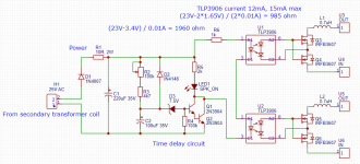
Ok... that tlp3096 is a useful part. I have never used one of those. Probably because I am usually panicking about getting a fet on or off in nanoseconds
Ok... that tlp3096 is a useful part. I have never used one of those. Probably because I am usually panicking about getting a fet on or off in nanoseconds
I just learned about this part two weeks ago myself. I think it was post by bmc0 or prasi... There is a whole thread called output relays on diyaudio
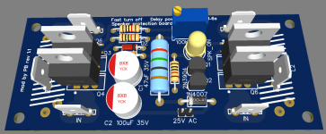
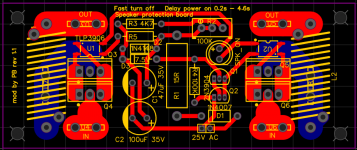
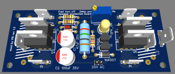
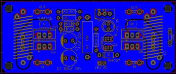
Latest update with all of the changes.
Added ability to bypass Thiele RL network - if only relay and protection options are required.
Added ground plain with its separate connector.
Added ability to bypass Thiele RL network - if only relay and protection options are required.
Added ground plain with its separate connector.
Attachments

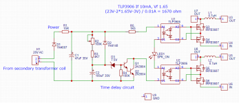
Intersting circuit.
Should you add a discharge resistor shunting C1 to ensure its voltage is "reset" when power is removed? Currently, it appears to me that when power is removed, C1 stops discharging when D3 stops conducting--- subsequent power on would have shortened delay because C1 and C2 will tend to retain stored charge.
Should you add a discharge resistor shunting C1 to ensure its voltage is "reset" when power is removed? Currently, it appears to me that when power is removed, C1 stops discharging when D3 stops conducting--- subsequent power on would have shortened delay because C1 and C2 will tend to retain stored charge.
And perhaps resistors shunting U1 and U2 outputs to ensure speedy discharge of gate capacitance when drive is released?
- Home
- Amplifiers
- Chip Amps
- Simple speaker protection board