Hi,
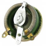
On atc monitors ( both active and passive) there is a potentiometer to 'compensate' bsc for inwall/closewall/ freestanding.
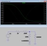
On active it is a high shelf filter centered at bsc freq attenuating mid high. On passive i don't know how its done but the analysis done here gives some clues.
Thank you all for this!
On passive it's also a high shelf centred at bsc frequency..On active it is a high shelf filter centered at bsc freq attenuating mid high. On passive...
Speaker boundary interference response.. I just had to look that up. Of course response and comb filtering is only the tip of the iceberg which needs to be considered if this is to be fixed.SBIR
It is interesting that there is some amount of shelving that averages the problems. If shelving is the option available to someone then it should be taken. What I find is the amount of success varies with the nature of the individual room/speaker interactions. I think the word 'compensation' helps to fit that description.
^For sure, anything that helps is good, speaker would work better near wall with ability to adjust the lows. Bass is very important, and can be quite annoying if too much. From the other perspective if asking does this make my speaker work near wall the answer is no, there is more to it than shelving the bass.
Hi Allen,
Thank you clarifying about Atc passive. Do you know which kind of circuit topology is used, i'm still curious about what they implemented ( i don't really care about values but how it's done)?
Thank you clarifying about Atc passive. Do you know which kind of circuit topology is used, i'm still curious about what they implemented ( i don't really care about values but how it's done)?
Last edited:
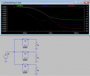
I can't imagine both woofers receiving the same signal since that would lead to power response issues. My bet is that the lower bass speaker has a lower xover frequency than the upper one. And is attanuated through the 25 W resistor. That would produce the curves shown.
Allen,
No i have no other info other than i have seen this potentiometer at the back of SCM300 ( or 200) passive, and i understood it was difficult to implement such shelve filter on passive xover. So i wonder how it could be implemented on such 'high power' passive xover.
No i have no other info other than i have seen this potentiometer at the back of SCM300 ( or 200) passive, and i understood it was difficult to implement such shelve filter on passive xover. So i wonder how it could be implemented on such 'high power' passive xover.
the manufacturer specifies a woofer X-over at 270 Hz, so that shouldn't be a problem.I can't imagine both woofers receiving the same signal since that would lead to power response issues.
https://www.revelspeakers.com/produ...forma3&dwvar_F208-_color=Black-GLOBAL-Current
Doesn't putting a series resistor with the woofer hurt the damping ratio?
Some of us spend a lot on low DCR inductors.
This method by Revel and possibly by other manufacturers, does it still belong in the 'audiophile' realm?
Some of us spend a lot on low DCR inductors.
This method by Revel and possibly by other manufacturers, does it still belong in the 'audiophile' realm?
Correct:
upper: Fhm = 2*Fs/Qts'
Qts': 2*Fs/Fhm
[Qts']: [Qts] + any added series resistance [Rs]: http://www.mh-audio.nl/Calculators/newqts.html
[Rs] = 0.5 ohm minimum for wiring, so may be higher if a super small gauge is used as a series resistor plus any added resistance from an XO/whatever.
upper: Fhm = 2*Fs/Qts'
Qts': 2*Fs/Fhm
[Qts']: [Qts] + any added series resistance [Rs]: http://www.mh-audio.nl/Calculators/newqts.html
[Rs] = 0.5 ohm minimum for wiring, so may be higher if a super small gauge is used as a series resistor plus any added resistance from an XO/whatever.
Hurt the damping ratio? Be careful before you judge, there is a lot of misleading information out there on this misunderstood topic. I would have no problem doing it. Can you be more specific about what your concern is?
'a series resistor with the woofer hurt the damping ratio' - you seem to have missed that the resistor is parallelled with your low DCR inductor
Not really.'a series resistor with the woofer hurt the damping ratio' - you seem to have missed that the resistor is parallelled with your low DCR inductor
We are discussing using a series resistor solely for attenuating the woofer level. No parallel inductor as that wouldn't make any sense in this application.
Please check out the earlier posts in this thread.
Sorry, my bad. I typed ' damping ratio' instead of ' damping factor' of the amplifier.Hurt the damping ratio? Be careful before you judge, there is a lot of misleading information out there on this misunderstood topic. I would have no problem doing it. Can you be more specific about what your concern is?
There is a lot of debate with regards to good damping factor of an amplifier. Some recommends 200 while others say anything above 20 is decent. But putting a 2.5 Ohm resistor in series with an 8 ohm woofer brings down the damping factor of an amplifier from 200 to about 3.
Isn't that bad?
Change is woofer Qts is different concern and can be easily simulated and accounted for in the design. Win ISD does a pretty good job.
No I wouldn't say it's bad, just different. I understood you meant damping factor, it was the word 'hurt' that I picked up on.
Damping Factor DebateThere is a lot of debate with regards to good damping factor of an amplifier. Some recommends 200 while others say anything above 20 is decent.
That article is an example of one that can cause a stir when talked about by those who don't have a certain handle on the workings of resonance... using words like control, and sentences like "it will move the way it wants to rather than the way the amplifier tells it to" are potentially misleading and make it sound like a bad thing... rather than necessary behaviour. Damping factor is simply an indicator of how much an amplifier behaves like a voltage source. People also use current sources and the results are predictable and the sound is good.
- Home
- Loudspeakers
- Multi-Way
- Boundary gain compensation


