
EDIT... please see following post for updated and revised files:
https://www.diyaudio.com/community/threads/output-transformers-for-dacs.327794/post-7018610
Hello everyone! I wish an excellent year to all DIY members and their families!
Hi Oneminde, thanks for kind words and welcome with your questions/suggestions 👍
Meanwhile I am presenting a universal PCB for Ian's DAC, which can be used in both passive and active output options. The active option is based on excellent-sounding matched 2sk170/2sj74 jfet pairs connected as a current followers means output buffer stage. What for is this active buffer after transformers? It's simple - to reduce the output impedance, which will expand the connection range of the following amplifiers or preamps with low input impedance to this board. The needed PSU for active part is 2x15V (+15V_GND_-15V). Poor quality PSUs will degrade all the benifits at once, thus the quality of PSU for these jfet buffers is significiant for SQ! Suggested to use UC/LTO based PSUs (Ian's "direction" of PSUs). The output DC-offset using matched jfets is in 0.1-0.5mV range from practice. To minimize the impact on the SQ, this version uses only matched pairs, without additional balancing resistors.
Also in this version of PCB I am providing the installation of current-voltage conversion resistors before transformers (RIVs). Despite the previously declared theoretical substantiation of the advantages in using transformers in current mode (without resistors in the primary), practice shows that the use of good-sounding low-resistance resistors in the primary winding allows to get a better sound.
There are three main options for this PCB:
1. BAL/SE Active
2. SE Active
3. Passive (BAL/SE)
Price for assembled board varies from $205 to $320 depending on the options (and componets) installed.
The design was renewed a bit as well placing both RCAs and XLR outputs in the right side of the PCB:
Questions and suggestions are welcome!
p.s. The layout has one mistake in routing. Please refer to this post, where you can find fixed gerbers
Attachments
Last edited by a moderator:
Forgot to mention in the previous post.
The output impedance after transformers (without active parts) at 1.4Vrms from Ian's 9038Q2MPiDM DAC is 4.7kOhm.
Whereas it can be bettered up to 10 Ohms (and even a bit less) using extra matched jfet pairs.
The output impedance after transformers (without active parts) at 1.4Vrms from Ian's 9038Q2MPiDM DAC is 4.7kOhm.
Whereas it can be bettered up to 10 Ohms (and even a bit less) using extra matched jfet pairs.
Hi bisesik,
I bought the transformers for TDA1541 and PCM63 few years ago (2019?). Recently I found it from shelf and I would like to start modifying my 1541 DAC. I am not sure about the connection for the primary and secondary of the transformer. Would you please show me the connection diagram? Is there any additional components required? like resistor, capacitor? Thanks in advance.
I bought the transformers for TDA1541 and PCM63 few years ago (2019?). Recently I found it from shelf and I would like to start modifying my 1541 DAC. I am not sure about the connection for the primary and secondary of the transformer. Would you please show me the connection diagram? Is there any additional components required? like resistor, capacitor? Thanks in advance.
Attachments
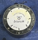
Hi! Regarding connection diagram - a bit later...
1) TDA1541's Iout (pin 25 for the right channel, pin 6 for the left channel) goes to "+prim" of the left (or right) transformer.
2) TDA1541's agnd (pin 5 for both channels) goes to "prim -" of both left and right transformers.
3) "+ sec" is the output (tip of RCA).
4) "sec -" is the gnd of the output (SE output I suppoose?) - tie "prim -", "sec -" and "Shield" pins together -> RCA's gnd.
5) You can use i/v resistor across the primary side, across the secondary side or across both sides. It is hard to catch more than 0.25V from the single TDA1541A without active components (for proper THD+noise and LF response). So for 0.25V you need to apply (third approach, i/v across both sides of transformer):
6) 100R across the primary coil and 1k6 across the secondary coil.
No need to use extra LPF capacitors.
1541->i/v resistor->trafo_with_loading_resistor->RCA

Understood. Thanks a lot!Hi! Regarding connection diagram - a bit later...
1) TDA1541's Iout (pin 25 for the right channel, pin 6 for the left channel) goes to "+prim" of the left (or right) transformer.
2) TDA1541's agnd (pin 5 for both channels) goes to "prim -" of both left and right transformers.
3) "+ sec" is the output (tip of RCA).
4) "sec -" is the gnd of the output (SE output I suppoose?) - tie "prim -", "sec -" and "Shield" pins together -> RCA's gnd.
5) You can use i/v resistor across the primary side, across the secondary side or across both sides. It is hard to catch more than 0.25V from the single TDA1541A without active components (for proper THD+noise and LF response). So for 0.25V you need to apply (third approach, i/v across both sides of transformer):
6) 100R across the primary coil and 1k6 across the secondary coil.
No need to use extra LPF capacitors.
1541->i/v resistor->trafo_with_loading_resistor->RCA
Hi Ivan,
Have you considered designing a two-tier architecture and using opamp as a buffer?
Have you considered designing a two-tier architecture and using opamp as a buffer?
Hello everyone! I wish an excellent year to all DIY members and their families!
Hi Oneminde, thanks for kind words and welcome with your questions/suggestions 👍
Meanwhile I am presenting a universal PCB for Ian's DAC, which can be used in both passive and active output options. The active option is based on excellent-sounding matched 2sk170/2sj74 jfet pairs connected as a current followers means output buffer stage. What for is this active buffer after transformers? It's simple - to reduce the output impedance, which will expand the connection range of the following amplifiers or preamps with low input impedance to this board. The needed PSU for active part is 2x15V (+15V_GND_-15V). Poor quality PSUs will degrade all the benifits at once, thus the quality of PSU for these jfet buffers is significiant for SQ! Suggested to use UC/LTO based PSUs (Ian's "direction" of PSUs). The output DC-offset using matched jfets is in 0.1-0.5mV range from practice. To minimize the impact on the SQ, this version uses only matched pairs, without additional balancing resistors.
Also in this version of PCB I am providing the installation of current-voltage conversion resistors before transformers (RIVs). Despite the previously declared theoretical substantiation of the advantages in using transformers in current mode (without resistors in the primary), practice shows that the use of good-sounding low-resistance resistors in the primary winding allows to get a better sound.
There are three main options for this PCB:
1. BAL/SE Active
2. SE Active
3. Passive (BAL/SE)
Price for assembled board varies from $205 to $320 depending on the options (and componets) installed.
The design was renewed a bit as well placing both RCAs and XLR outputs in the right side of the PCB:
View attachment 1015164
View attachment 1015172
Questions and suggestions are welcome!


Hi bisesik,
I found that the TDA1541 that I built sound so low volume. What's the disadvantage if I increase the output voltage? (increase the 1.6k resistor?)
And I have another transformer for PCM63 that I would like to build soon, would you mind tell me the resistors to use? What should the resistors to use if I use:
1. One PCM63
2. Two PCM63 in parallel
Thanks again!
Hi,Hi bisesik,
I found that the TDA1541 that I built sound so low volume. What's the disadvantage if I increase the output voltage? (increase the 1.6k resistor?)
And I have another transformer for PCM63 that I would like to build soon, would you mind tell me the resistors to use? What should the resistors to use if I use:
1. One PCM63
2. Two PCM63 in parallel
Thanks again!
In accordance with my notes your trafos was ~ 1:6. So 1.6k across the secondary gives you ~0.35V of the signal. Sure you can increase the resistor across the secondary to get louder signal. Disadvantage will be a shifted response at LF, but depending on your system you can simply not sensing it. So no doubts you can try.
Single PCM63 has a similar output capability as TDA1541, so similar approach is OK here as well. Two PCM63 in parallel will give you a doubled signal (simple story). Better to know the input properties of the next stage (amp/preamp) such as input impedance and sensetivity to provide you the needed resistors values.
~10kOhm@20HzHi
what is the output impedance on the V out trafo
Best Bjarne
Sure you can, but I simply not see advantages compared with the simplest jfet buffer. As for me - this will be the addition of extra entities 😒Hi Ivan,
Have you considered designing a two-tier architecture and using opamp as a buffer?
Sorry I have a few more questions about PCM63:Hi,
In accordance with my notes your trafos was ~ 1:6. So 1.6k across the secondary gives you ~0.35V of the signal. Sure you can increase the resistor across the secondary to get louder signal. Disadvantage will be a shifted response at LF, but depending on your system you can simply not sensing it. So no doubts you can try.
Single PCM63 has a similar output capability as TDA1541, so similar approach is OK here as well. Two PCM63 in parallel will give you a doubled signal (simple story). Better to know the input properties of the next stage (amp/preamp) such as input impedance and sensetivity to provide you the needed resistors values.
1. According to the datasheet, there are pinouts RF1 and RF2 that connects to the op-amp or left opened if not in used. So I just left open them?
2. The BPO pinout - Bipolar Offset Current Output (+2mA) still connects to Iout?
3. What should I connect for Vpot (Bit Adjust Reference Voltage Tap (–3.52V)*)?
Thanks again Ivan.
Last edited:
Yes1. According to the datasheet, there are pinouts RF1 and RF2 that connects to the op-amp or left opened if not in used. So I just left open them?
Yes2. The BPO pinout - Bipolar Offset Current Output (+2mA) still connects to Iout?
There is a dedicated circuit in the datasheet for this (Figure 5). As it called "Optional Bit-2 Adjustment Circuitry" then it is up to you if use it or not.3. What should I connect for Vpot (Bit Adjust Reference Voltage Tap (–3.52V)*)?
Thanks Ivan.Yes
Yes
There is a dedicated circuit in the datasheet for this (Figure 5). As it called "Optional Bit-2 Adjustment Circuitry" then it is up to you if use it or not.
I checked the transformer's resistance before any connection: primary is about 7R, secondary is about 700R. So I use 100R for primary, 1.6k for secondary, are these resistor values correct?
Last edited:
Forget about coils resistances at DC as music is AC.
I have checked (~2.5 years have past already😳). The turns ratio of your transformers for PCM63 are 1:4.
Thus:
100R||1600R/(4*4)=100||100 means excellent impedances allocation for best signal power transferring through the trafos.
The impedance seen by PCM63 is 50R. Good.
Then (including internal losses) after transformers you should get 0.25Vrms @ 800R impedance
Understood. Thanks a lot.Forget about coils resistances at DC as music is AC.
I have checked (~2.5 years have past already😳). The turns ratio of your transformers for PCM63 are 1:4.
Thus:
100R||1600R/(4*4)=100||100 means excellent impedances allocation for best signal power transferring through the trafos.
The impedance seen by PCM63 is 50R. Good.
Then (including internal losses) after transformers you should get 0.25Vrms @ 800R impedance
Today's acoustic recordings of the whole system im my small (~9 sq.m) listening room. Output power (1kHz sine measured on speakers is ~1W). Mics are on listening point.
A) Digital to analog part:
1. x86 PC with Euphony OS+Roon+HQP (44->352.8 / ext3 filter/NS9 dither)
2. NAA on BBB as endpoint for HQP
3. BBB' I2S (16 bit limited) -> fifopi (DRIXO 22.5792MHz clock)-> reclockpi -> pcm_board -> TDA1541AS2 (+ Abbas' tube dem clock)
B) Analog part:
1. TDA1541AS2' Iout -> my IV resistors -> my big trafos+jfet buffer -> my big trafos+jfet buffer ->
2. -> my interstage cables -> modified chineese 845 tubes based' SE amplifier-> my speaker cables -> acoustic panels + vintage Heil AMT1 HF speakers
C) Analog to digital part:
1. Ribbon mics -> Benchmark ADC1+DRIXO 24.576MHz -> USB out ->
2. -> Pixel phone + Audio Evolution recording app
3. 96/24 -> 48/16 mp3 using Soundforge 11
Last edited:
- Home
- Vendor's Bazaar
- Output transformers for DACs