How is the heat?Here’s a newly born Aleph 60 mono in deluxe 4U chassis with Antek as-4225 and 400va donut cover. I need to finish making the other channel. It sings nicely on the test speaker. It is also very quiet on my test speaker and headphone hum tester. The real test will be on horns. I need to get covers on and let it cook for a long time.
Does anyone know of nice hole plugs to fill in the other side of the rear plate? I would like some black plastic plugs to close up the extra input and speaker terminal holes.
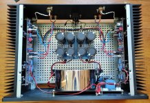
Randy,Here’s a newly born Aleph 60 mono in deluxe 4U chassis with Antek as-4225 and 400va donut cover. I need to finish making the other channel. It sings nicely on the test speaker. It is also very quiet on my test speaker and headphone hum tester. The real test will be on horns. I need to get covers on and let it cook for a long time.
Does anyone know of nice hole plugs to fill in the other side of the rear plate? I would like some black plastic plugs to close up the extra input and speaker terminal holes.
Looks great! This thread is really trying to torpedo my plan to slowly and carefully join the ranks of Fearless Amplifier Builders. I have just about finished my first, an ACA mini. Plan to was to follow that up with Aleph J or M2X to bring in the complexity of the discrete power supplies. But now I just want to jump straight to the finish to an Aleph 60, must resist the temptation.
One question, any reason you didn't run the wire to connect the expansion amplifier board across the front of the chassis using the front expansion ports? Trying to dodge the rectifiers? To the novice like myself I would think to run it across the back where the mains AC is coming in and speakers outs are crossing. Of course with that tight twist you have on the wiring bundle I doubt its picking up an interference.
Thanks again for this project, I am going to be patient but I can't wait to get there.
@woodturner-fran: I need to put the covers on and let it cook. I'll report back with some heat measurements. I got distracted last night by recapping a B&K ST-140. That's done, so back to this A60 project.
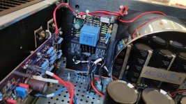
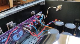
@CoGT3: I was 50/50 on running that twisted wire bundle front or back. I wanted to stay away from rectifiers. I also wanted to bundle all wires to keep the loop area small. So the short PSU wires come up and run with the speaker wires and daughter board bundle. The bundle is perpendicular to the input AC. My thought process was to try it this way, and if it's noisy I could try the front by flipping the expansion board easy enough. Turns out it's dead quiet on my headphone tester, so I think I'm going to follow the Jim 6L6 wisdom and put the lid on and enjoy.
@CoGT3: I was 50/50 on running that twisted wire bundle front or back. I wanted to stay away from rectifiers. I also wanted to bundle all wires to keep the loop area small. So the short PSU wires come up and run with the speaker wires and daughter board bundle. The bundle is perpendicular to the input AC. My thought process was to try it this way, and if it's noisy I could try the front by flipping the expansion board easy enough. Turns out it's dead quiet on my headphone tester, so I think I'm going to follow the Jim 6L6 wisdom and put the lid on and enjoy.

Today I finished some details and took a few pictures. At this time i want to thank Randy again for providing this universal aleph PCBs, using the fantastic diyaudio UMS standard. Switching from M2x to A30 was an easy task. Total cost of this project was around 200 Euros (because I could use the M2x enclosure and power supply)
I did not measure AC current gain yet but I took a first listening session. Compared to the M2x it sounded louder and more direct. The Bass is on a whole different level, more impact and better defined. I guess that is because M2x is less capable to drive my 4 ohm Arcus speakers.
I instantly missed the "magic" mid- and highrange sound the M2x delivers, but the Aleph30 has its own qualities as I discovered later on. I found myself listening on higher SPL Levels on the long run, to add some volume to voices and percussion. Highs still sound a bit dull with my speakers. But it was a pleasure to listen to some of my reference records. I could have listened all night long.
Next step is to measure and set AC current gain to 50%. I also read about interesting modification of Aleph amplifier circuits:
- filter frontend supply rails with 220R / 220uF to achieve better PSU ripple rejection
- check high frequency sine wave distortion waveform at high levels, experiment with higher values for MICA compensation cap C8 to achieve a cleaner sine wave response
- use different MOSFETs for the input stage
- create an own layout to merge M2x Frontend with Aleph30 Backend 😂😂
Attachments


Thanks Anand. Maybe I will choose a thermostat with a lower value for even more protection. As it is implemented now it won't protect the output MOSFETs too much but I hope it can protect me from a fire if anything bad happens.@AddiDub
I like the KSD-01f 75deg C thermostat you have implemented on each channel, a nice safety feature.
Regards, Addi
Indeed, I was discussing with a colleague in the industry yesterday, and he recommended 65 degrees C as a safer option.Thanks Anand. Maybe I will choose a thermostat with a lower value for even more protection. As it is implemented now it won't protect the output MOSFETs too much but I hope it can protect me from a fire if anything bad happens.
Regards, Addi
Best,
Anand.
Hi Addi, great work!
Could you please tell more about the use of the thermostat?
Do you use it in combination with the protection circuit?
Could you please tell more about the use of the thermostat?
Do you use it in combination with the protection circuit?
Thanks for the hint, @Eric ! I will check for certified thermoswitches. @Plott the thermoswitches where included in a cheap China-made soft start circuit that I use instead of the CL-60. I can't say if they really shutdown at 75°C, but I tried to trigger the thermostats using my BZ10 Espresso machine and they eventually shut off. By the way the BZ10 was a great help to learn to be a fearless amplifier builder, because it's so hot...
Edit: it's nice to see all of you here, If I remember right some of you guys participated in my group buy of 2sk170 last year 🙂
Edit: it's nice to see all of you here, If I remember right some of you guys participated in my group buy of 2sk170 last year 🙂
AddiDub - you have sparked a good idea for experimentation here!Next step is to measure and set AC current gain to 50%. I also read about interesting modification of Aleph amplifier circuits:
- filter frontend supply rails with 220R / 220uF to achieve better PSU ripple rejection
I'm tempted to try this on a prototype basis. I will be sending boards to fab for GB2 in a few days. So it's easy to add a few more boards to my order.
I could make some prototype boards with added C or CRC on board. It will probably mean going from a 4+4 MOSFET to a 3+3 format so I could gain additionional real estate on the board for the caps. 3+3 MOSFETs is good for Aleph 30 or Aleph 5 on a single board. Bigger amps could still use the expansion boards.
Any thoughts on adding the CRC's as shown in the green boxes? Or just try a C? Or RC only?
With 200R on negative rail and roughly 24 mA of LTP current, how will the lower output FET get correct bias?
@rhthatcher I was just collecting ideas. I am in no way qualified to decide if it is possible to add a RC filter to the frontend. I was hoping for some discussion like @Marcus Halberstram comes up with..
@rhthatcher
You might consider measuring the actual ripple while under load @ the R11/C11 node with the supply you have recommended in the build doc. I do know that in my build, where I’ll be using a ripple eater it will most likely be superfluous.
It’s a great thought to experiment though - I’m curious!
Best,
Anand.
I don't have unobtanium parts, but I've used FQP3P20 matched pairs here and find them to be a worthwhile improvement over the 9610s. Start with 50% AC gain and go from there. The 3P20s are working well for me at 45%AC gain.Next step is to measure and set AC current gain to 50%. I also read about interesting modification of Aleph amplifier circuits:
- use different MOSFETs for the input stage
Just my 2.2Ω on the matter..
I frequently install capacitors in the roles of C21 and C23 on my PSU boards. These are intended to lower the impedance of the bulk capacitors on the main rails. I typically use 1000 uF or 2200 uF audio grade caps. There is usally a way to sneak them onto the PCB, even the Univrsal PSU boards from the store. Having spots for these caps on the main amp boards can be nice as well.
The remaining RC components for the front end diff pair are perhaps less beneficial. If implemented properly, the current source driven by Q3 will have sufficient filtering to achieve good PSRR performance. The tail of the diff pair alrady has high impedance to the negative rail.
@TungstenAudio so in your opinion it would make sense to place two local decoupling capacitors directly to the amp pcb, but no additional RC networks?
That is what I would do. Making room for a decent size cap, so 5mm and 7.5mm lead spacing, 12mm body diameter.
- Home
- Amplifiers
- Pass Labs
- Classic Aleph Amplifier for Modern UMS Chassis Builder's Thread