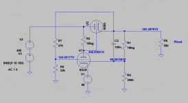
Hello. I am learning about series pass regulators. I have breadboarded the following regulator, which works fine but at startup the output voltage climbs well past output target of 270V - goes all the way to 365V (ie. the input voltage) before settling down. Can someone suggest how i can correct this? I just want it to climb to 270V and stay there.

Cold cathode glow discharge tubes such as your V3 and V4 have an ignition delay. You can reduce it by putting a source of radioactivity right next to them, if they have no radioactive primer built in, or by shining light on them (depending on the material used for their cathodes).
You can find more information about this in section 4 of https://linearaudio.net/sites/linearaudio.net/files/03 Didden LA V13 mvdg.pdf and in the references mentioned in section 4.
In what order of magnitude is the length of the overshoot? Seconds, milliseconds?
You can find more information about this in section 4 of https://linearaudio.net/sites/linearaudio.net/files/03 Didden LA V13 mvdg.pdf and in the references mentioned in section 4.
In what order of magnitude is the length of the overshoot? Seconds, milliseconds?
Last edited:
So it goes like this:
Powerup -> 270V about 20 seconds
270V -> 365V another 5 seconds
365V -> 270V about 10 seconds
Powerup -> 270V about 20 seconds
270V -> 365V another 5 seconds
365V -> 270V about 10 seconds
Shouldn't there be a high value resistor bypassing one of the glow discharge tubes to make sure they both ignite fast?
Yes, there should, good point. I don't know whether it should preferably be connected across V3 or across V4.
Probably it doesn't make much difference. I would choose V4 and put a 100K resistor in parallel to it.
No, VRs ignite at about T+12 seconds.At what moment do the glow discharge tubes ignite? At the end of the 365 V part?
Probably it doesn't make much difference. I would choose V4 and put a 100K resistor in parallel to it
Add this made no difference.
This looks like normal behavior for your circuit. Unfortunately a gas VR tube has to reach the strike voltage which is higher than operating voltage.
One thing you can do is add a small resistor across one of the VR tubes to cause a small imbalance and one will start earlier.
You may need to look for other circuits if you really need a slow ramp up voltage with no overshoot.
One thing you can do is add a small resistor across one of the VR tubes to cause a small imbalance and one will start earlier.
You may need to look for other circuits if you really need a slow ramp up voltage with no overshoot.
By the way, are those 12 seconds more or less reproducible or do you get a different delay every time you try?No, VRs ignite at about T+12 seconds.
If voltage is applied to cold tubes, would the vr tubes not ignite immediately? They're directly across the incoming voltage.
Not necessarily. The ignition delay can be microseconds to seconds, depending on the cathode material and the amount of radioactive primer or the amount of light shining on them.
Splitting R4 into two resistors of 220 kohm and putting a big capacitor (at least 220 uF) to ground at the mid point is probably the least inconvenient fix. The first 220 kohm resistor has to be at least a 1 W type, but preferably 2 W.
Last edited:
That will not improve anything if the glow discharge tubes ignite in time - which they do according to post #8, although I don't know if they do so reproducibly.VR tubes should ignite much before other tubes start to conduct. That is the fact.
You could eliminate 0C3 and take the screen voltage of error amplifier from a voltage divider as in attached schematic.
Edit: maybe it will improve the line regulation a bit, due to higher voltage drop across the resistor supplying V4. Then again, it could also get worse due to the unregulated screen grid voltage.
Last edited:
The other problem aside from vr tube startup is the 12j7 needs to pull down the grid of the pass tube. If the pass tube warms up first the output will rise past expected voltage.
- Home
- Amplifiers
- Tubes / Valves
- Tube regulator goes over target voltage then settles