Well i don't want to go anywhere near cd4440 or la4440 chip . I hate this amp to my heart content . It was my first amp . And still i think i wasted my money .
Sinclair Super IC-12
It blew up if you talked loudly in the the other end of the room.
After having blown up 3 pieces I was almost giving up electronics as a hobby.
Cheers, Martin
It blew up if you talked loudly in the the other end of the room.
After having blown up 3 pieces I was almost giving up electronics as a hobby.
Cheers, Martin
As much as I loved Clive Sinclair's inventions the IC 12 was dreadful never got one working for more than 20 minutes
Trev
Trev
The irs2092 takes a little while to get to grips with.
Took a couple of pcb reworks before I could get a reliable output.
I was using mosfets with high capacitance gates and the 2092 didnt like it.
I had to use gate drivers to drive them hard enough.
The 2092 was seeing mosfets turn on slowly and assumed an overload.
Not a bad chip once you get to know it.
Or just stick to application note layouts etc.
They are just cheap noisey crap though 🙂I used LM386 a no of times never had a problem with them
Trev
LA4425. Since the TDA2003 was discontinued, I thought this would be a nice replacement with fixed gain and low part count. It has the gain set too high and very noisy.
TDA7240. This was a bridged output chip in a TO-220 package (7 pins). It was prone to oscillation. I tried playing around with the layout and got it usable, but it didn't seem to like long speaker leads. It might have been tamed with an inductor on the output but I never pursued it.
TDA7240. This was a bridged output chip in a TO-220 package (7 pins). It was prone to oscillation. I tried playing around with the layout and got it usable, but it didn't seem to like long speaker leads. It might have been tamed with an inductor on the output but I never pursued it.
Can you tell me how bad it was? Identical to LM1875 but price is higher. I guess it's not for audio.LM675
Years ago, I discovered that you cannot use too much feedback on a LM377, and more recently I found the same problem upgrading the circuit around a commercial mini stereo, which had a similar part. But once I reduced the feedback to a stable system, it sounded great and ran cool. I think a lot of "bad sound" is actually instability due to over optimistic feedback levels. When the data sheet saz "minimum gain", you need to pay attention. A resistor between the + and - inputs is a simple solution.
"The amplifier is also internally compensated for gains of 10 or greater."
"The amplifier is also internally compensated for gains of 10 or greater."
Last edited:
TDA7297 as it sounds better than some discrete amplifiers I built. I think I should build a Korg Nutube device as compensation.
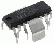
deep in the past, back in socialist era, we had to use this chip a lot, MBA810, dreadful sound
https://www.ebay.com/itm/133256234978
https://www.ebay.com/itm/133256234978
We knew it as a TBA810. That was definitely up there in the worst ever 🙂 Used a lot in TV's and one make and model had two identical plug in PCB's, one was audio output and one was frame output. The output coupling caps used to fail (high esr) on the frame stage giving frame cramp at the bottom of the screen so the quick fix a lot of techs used was just to quickly swap the boards over.deep in the past, back in socialist era, we had to use this chip a lot, MBA810, dreadful sound
TDA3000's in a 7 pin TO220 package used to give us problems as well. An interesting chip but we had a lot fail.
TBA 810M was my first chipamp (using with a FM kit), i still remember those wonderful days. It was very popular back then 🙂
- Home
- Amplifiers
- Chip Amps
- Your most hated chip amp
