I like the idea of having the option to place my speakers either far away or very close to the front wall, whatever the situation demands, with the convenience of a flick of a switch. I didn't know if it was actually possible until I saw the 'Normal/ Boundary' adjustment knob at the back panel of Revel F208.
Does anyone have any idea how this could be implemented? One of the photo I saw suggests this is done with resistors only.
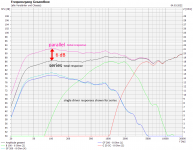
I have attached some photos of what the boundary compensation actually does. Basically, it reduces the level by 4dB around 100Hz in a gradual slope from 400Hz.
It does not attenuates the very low frequencies by much.


Does anyone have any idea how this could be implemented? One of the photo I saw suggests this is done with resistors only.
I have attached some photos of what the boundary compensation actually does. Basically, it reduces the level by 4dB around 100Hz in a gradual slope from 400Hz.
It does not attenuates the very low frequencies by much.
The simplest idea would probably be closing/stuffing bass reflex ports when moving speakers to the wall.Does anyone have any idea how this could be implemented?
Alternatively you could have two different baffle step compensation networks that can be switched (that means attenuating mid-treble more or less).
This is done for normal and "hwg" (near wall) version of this speaker:
https://heissmann-acoustics.de/en/bausatz-cinetor-monacor-sp6-100pro-dt-300-wg-300/
The different response graphs are shown here:
https://www.diy-hifi-forum.eu/forum/showthread.php?7471-Unterschied-Cinetor-Standard-und-HWG
The revel probably allows switching one of both woofers off for near-wall placement.
Last edited:
See the second photo I have posted. Blue line is ideal to counter boundary gain. Red line is the simple trick of plugging the port.The simplest idea would probably be closing/stuffing bass reflex ports when moving speakers to the wall.
Alternatively you could have two different baffle step compensation networks that can be switched (that means attenuating mid-treble more or less).
The revel probably allows switching one of both woofers off for near-wall placement.
There is substantial difference. Closing the port will still make your 100Hz region bloated in near wall placement.
Two different baffle step network will mean that for one of the setting frequencies above the baffle step will be hotter.
But as you can see in the case of the revel, only the level of the bass frequencies change. So I don't think they are using two different networks with different BSC levels.
Switching off one woofer? I don't think so too. Otherwise, I'd have read about it in reviews as it is too weird not to share!
what you are looking for is room equalization. it will just take a PEQ or two if all you want to do is compensate for boundary gain. and if that is all you do, then you won't hurt the SQ by trying to correct too much
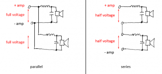
Well, you have a x-over frequency of 270 hz and can switch an attenuation of about 6 dB. Maybe they change woofers from parallel to series? ... Rather complex with crossover part values, but possible.Switching off one woofer? I don't think so too.
Everyone knows about room equalization.what you are looking for is room equalization. it will just take a PEQ or two if all you want to do is compensate for boundary gain. and if that is all you do, then you won't hurt the SQ by trying to correct too much
You have any idea how Revel is doing it in passive crossover level? The idea is to learn something new.
Can you trace the xo schematic and the model it in an XO program?
That would answer your question. If not, I would model a generic XO and see the effect of adding resistance in series with the woofer or an Lpad to the woofer. From the measurements, most of what changes is peak SPL from the woofer. Some R is added that reduces the drive level and flattens the peak.
That would answer your question. If not, I would model a generic XO and see the effect of adding resistance in series with the woofer or an Lpad to the woofer. From the measurements, most of what changes is peak SPL from the woofer. Some R is added that reduces the drive level and flattens the peak.
The two woofers are in parallel and so the crossover is designed for 4 ohms. If you disconnect one of the woofers the crossover network will see 8 ohms and that will change quite a lot of things.Well, you have a x-over frequency of 270 hz and can switch an attenuation of about 6 dB. Maybe they change woofers from parallel to series? ... Rather complex with crossover part values, but possible.
Anyone who wants to use this speaker for boundary placement will get the performance of only one woofer, so I do not think Revel designed it this way. And none of the reviews I read mentioned one of the woofer not working. I don't think anyone will forget to mention such a thing.
That's why i said: it is complex regarding x-over parts having to change, too. But, anyway, i'm out, just tried to give my thoughts.If you disconnect one of the woofers the crossover network will se
Adding series resistance to LF driver is out of question.Can you trace the xo schematic and the model it in an XO program?
That would answer your question. If not, I would model a generic XO and see the effect of adding resistance in series with the woofer or an Lpad to the woofer. From the measurements, most of what changes is peak SPL from the woofer. Some R is added that reduces the drive level and flattens the peak.
I was hoping for a parallel network.
But most likely they are using a low pass with higher attenuation on one of the woofers in 'boundary' setting.
That also explains lower attenuation below 70Hz.
Which means this won't work in single woofer system.
what KEF does in its high end is provide two different length port tubes which is something we DIYers could copy with little difficulty
Port tuning change is more targeted at room gain, not boundary gain. You need to target 100-200Hz too for boundary compensation. Think about varying BSC.what KEF does in its high end is provide two different length port tubes which is something we DIYers could copy with little difficulty
You are probably on the right track here. It is possible that this is not a three-way system but a 3.5 way. In this case they just chnge the crossover point of the lower woofer in order to get this dip. Or maybe it is really three-way and the flip of the swithc makes it a 3.5 way.But most likely they are using a low pass with higher attenuation on one of the woofers in 'boundary' setting.
That also explains lower attenuation below 70Hz.
Which means this won't work in single woofer system.
Another trick might be a parallel notch in series of the woofers.
Regards
Charles
Looks pretty straight forward to me. The pics attached in post #1 show 2 switches and 5 resistors attached to the board.

The tweeter adjustment switch has 5 positions and there are 4 low wattage (10W) resistors and 1 straight wire across the terminals above R5. So that will take care of the 5 tweeter adjustments. So that leaves a single 25W 2.5ohm resistor for the other switch to adjust the LF's.
And just to double check, I pulled up a random 3-way sim from my files and put 2.5ohm in front of the woofer (in series), in this case the Dayton RS225-8. Results are pretty much exactly what your Revel graph displays above.

Orthodox? Absolutely not. But if it works..........
The tweeter adjustment switch has 5 positions and there are 4 low wattage (10W) resistors and 1 straight wire across the terminals above R5. So that will take care of the 5 tweeter adjustments. So that leaves a single 25W 2.5ohm resistor for the other switch to adjust the LF's.
And just to double check, I pulled up a random 3-way sim from my files and put 2.5ohm in front of the woofer (in series), in this case the Dayton RS225-8. Results are pretty much exactly what your Revel graph displays above.
Orthodox? Absolutely not. But if it works..........

Might have been obvious. But I really didn't expect a series resistance added to the woofers.Looks pretty straight forward to me. The pics attached in post #1 show 2 switches and 5 resistors attached to the board.
View attachment 1031218
The tweeter adjustment switch has 5 positions and there are 4 low wattage (10W) resistors and 1 straight wire across the terminals above R5. So that will take care of the 5 tweeter adjustments. So that leaves a single 25W 2.5ohm resistor for the other switch to adjust the LF's.
And just to double check, I pulled up a random 3-way sim from my files and put 2.5ohm in front of the woofer (in series), in this case the Dayton RS225-8. Results are pretty much exactly what your Revel graph displays above.
View attachment 1031217
Orthodox? Absolutely not. But if it works..........
They discarded this in later models.
ok, i was not out yet ;-) - and realized it is not at all complex.That's why i said: it is complex regarding x-over parts having to change, too. But, anyway, i'm out, just tried to give my thoughts.
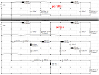
you just use an independent x-over network for each driver (calculated for the respective impedance of the single driver) and you can simply switch parallel and series without changing response of each driver.
as an example i just took an arbitrary boxsim-project with 2nd order slopes and ~500 Hz woofer-mid x-over frequency.
attached the network and simulated response. result is the 6 dB diference, similar to the one shown in your 3rd image, although due to shallow slopes and high x-over frequency (plus woofers playing quite high into midrange are) in my simulation the midrange is more affected.
Attachments
Last edited:
The post above by JReave makes perfect sense though.ok, i was not out yet ;-) - and realized it is not at all complex.
you just use an independent x-over network for each driver (calculated for the respective impedance of the single driver) and you can simply switch parallel and series without changing response of each driver.
Your idea might work too but does series crossover network work that way?
it does, see two possible explanations, each based on a single woofer circuit with respective x-over-values.Your idea might work too but does series crossover network work that way?
the response does not change whether you connect the identical(!) "woofer+inductor+cap-cells" in parallel or in series.
this was just to check feasibility of the parallel/series switch, referring to your picture number 3.
for real rooms, changing the woofer level by 6 dB may be too much to correct for placement, so JReave's solution will make more sense.
Attachments

Last edited:
just came across this implementation of near-wall/free standing switch:
http://speakerdesignworks.com/Finalists_4.html
http://speakerdesignworks.com/Finalists_4.html
^that is how I thought about this subject at first, attenuate mid and tweet, a baffle step compensation made easy with 3 way design + resistor. Never done passive xo though so I don't know how people actually do this.
Doing it electronically like this with a speaker that is otherwise designed to be positioned into the room is a slap on fix although better than nothing when there is no possibility to have the speaker where it was designed for. For near /on wall there is whole set of requirements that would make difference for better if baked in from the start. I'd consider things on the whole construct such as how to address SBIR, toe in, position of binding posts and possible port, number of ways and how to construct each and so on 🙂
Due to the same boundary that boosts the bass "that needs cutting" starts comb filter where wavelength is shorter than ~8x distance to the front wall. Basically, when the direct and reflected sound have path length difference shorter than 1/4wl there is only constructive interference and frequencies above that there is dips and peaks, alternating destructive and constructive interference. The audibility / effect can be adjusted by attenuating the sound towards the wall and/or absorbing it at the wall. In general, speaker designed for on wall use should work fine further in room as well other than perhaps having light bass, in which case the adjustable crossover boundary gain compensation switch would be nice 😉
Anyway, the takeaway is that there is not just the boundary gain happening on low frequencies but also comb filter above.
Last edited:
- Home
- Loudspeakers
- Multi-Way
- Boundary gain compensation