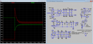
The order is unimportant as long that is what you want to see /expect. The simulator just do one after another with the condition(s) you assigned so you can view all the results in one window. In this case we see 2 views. But you have another view, that is the problem when they don't agree.
I know why. Like this: The 2 generators V1, V2 are AC so it's not Ohms Law in your view, change V1 V2 to DC 150V, it displays your view, one normal and one shorted. Ah so if you DC source then it is all over?
I know why. Like this: The 2 generators V1, V2 are AC so it's not Ohms Law in your view, change V1 V2 to DC 150V, it displays your view, one normal and one shorted. Ah so if you DC source then it is all over?
Last edited:
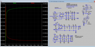
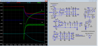
Yes, I would certainly expect that the order should be unimportant, and that the simulation starts from scratch for each choice of the step parameter. So for the case RT1=1 ohm, your simulation shows what happens if you power up the amplifier, with the upper tube already shorted across by the 1 ohm resistor RT1. As one would expect, the current through the speaker then builds up from zero, in the way you are seeing in your plot.The order is unimportant as long that is what you want to see /expect. The simulator just do one after another with the condition(s) you assigned so you can view all the results in one window. In this case we see 2 views. But you have another view, that is the problem when they don't agree.
I know why. Like this: The 2 generators V1, V2 are AC so it's not Ohms Law in your view, change V1 V2 to DC 150V, it displays your view, one normal and one shorted. Ah so if you DC source then it is all over?
That is all fine, and everything seems to be working exactly as you have simulated it. However...
That is not the simulation one should be doing if one wants to study the effect of a catastrophic tube failure while the amplifier is already running. To study this, one should have the capacitors already charged up to their full voltages, and only at this stage should RT1 be abruptly set to 1 ohm, simulating the sudden tube failure. As I've said, one hardly needs LTSpice in order to see what will happen, especially if it is agreed that the cutout relay will trip 15 milliseconds after the catastrophe, so that one only needs to work out what happens during those 15 milliseconds. Making a few approximations, like neglecting the comparatively small current through the lower tube, and neglecting the fact that actually some recharging of the main capacitors will be going on during those 15 milliseconds, one can essentially see that the voltage across the 1+1+8 = 10 ohm load will begin an exponential-type decay that starts from 150V, and after 15 milliseconds would have reached about 103V. So the current through the speaker starts out at about 15 amps at the onset of the catastrophe, falling to something of order 10 amps at 15 milliseconds. If the relay then opens, one has about 100V across the opening contacts, with about 10 amps flowing just at the instant of separation. That, as I understand it, has the possibility to create a very substantial arc. That is all I have been trying to say.
I already explain your view /calculations can only be met / true if the generator is DC source which is not the case. What is your view on that (AC)? Timing relay is only possible when your have AC source. How confusing.
one should have the capacitors already charged up to their full voltages,
Of course, it starts with zero voltage at speaker, how it's possible if HT/cap is not =+-150V? Do you mean +75/-150V to start with, of course not.
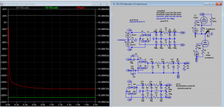
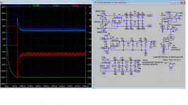
Not everyone is clear about this, so another snapshot could help? Attach PSU of DC /Battery source. when upper tube is shorted. it's 10A everywhere.
one should have the capacitors already charged up to their full voltages,
Of course, it starts with zero voltage at speaker, how it's possible if HT/cap is not =+-150V? Do you mean +75/-150V to start with, of course not.
Not everyone is clear about this, so another snapshot could help? Attach PSU of DC /Battery source. when upper tube is shorted. it's 10A everywhere.
Attachments
Last edited:
I would assume that there must be ways, in LTSpice, to set up a simulation where the (AC powered) amplifier is powered up, allowed to settle into a steady-state (and fully functioning) condition, and then at that point the value of RT1 is abruptly set to 1 ohm. That would give a reasonable simulation of a catastrophic tube failure that takes place after the amplifier is running. I am not myself familiar enough with LTSpice to know how one would do that, but it sounds like something that should be possible, I suppose.I already explain your view /calculations can only be met / true if the generator is DC source which is not the case. What is your view on that (AC)? Timing relay is only possible when your have AC source. How confusing.
one should have the capacitors already charged up to their full voltages,
Of course, it starts with zero voltage at speaker, how it's possible if HT/cap is not =+-150V? Do you mean +75/-150V to start with, of course not.
Not everyone is clear about this, so another snapshot could help? Attach PSU of DC /Battery source. when upper tube is shorted. it's 10A everywhere.
But actually, as I've said, it is easy enough to get a pretty good idea of what would happen in the first 15 milliseconds or so without even needing LTSpice.
One way is perhaps to use RT1 600 ohm divide it into many smaller steps, many be 10 ohms step, so the 1st step is very close to HT/Cap voltage.
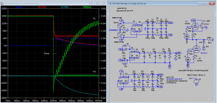
There is a Switch in the MISC component section which can be timed ...I would assume that there must be ways, in LTSpice, to set up a simulation where the (AC powered) amplifier is powered up, allowed to settle into a steady-state (and fully functioning) condition, and then at that point the value of RT1 is abruptly set to 1 ohm.
Attachments
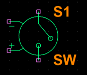
Thank you. I am quite familiar with that switch, how come I haven't thought of that. Have fun.
Attachments
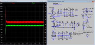
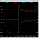
That looks good. There's that 15amp or so initial peak in the speaker current, then trending downwards.Thank you. I am quite familiar with that switch, how come I haven't thought of that. Have fun.
Do you have any problem? The current in the speaker is quite similar to 1k resistor.
no problem, when from the start is decided that i am using an output coupling capacitors....
I know I raised this point before, but I still think it is one that is worth considering. If you are bypassing the 1K R33 resistor, then this means that in the event of a catastrophic tube failure the live speaker terminal could be driven either positive, to close to +150V if the failure affects the upper tube, or it could be driven negative, to about -150V if the failure affects the lower tube instead. The odds are 50-50 for which way it could go.no problem, when from the start is decided that i am using an output coupling capacitors....
This means that if one is going to implement a series capacitor as a protection mechanism, it needs to be an unpolarised capacitor. A polarised capacitor that is being driven "the wrong way" with 150V is likely to break down almost instantly. Given the large value of capacitance that is needed for the purpose, this means one would have to use two electrolytic capacitors in series, connected back to back. Of course each needs to be double the capacitance that one actually desires for the composite series capacitor.
It seems to me that it would otherwise be somewhat illogical, to opt for using a series capacitor as the protection mechanism but then to use just a single polarised capacitor, since this would be guaranteed to be ineffective as a safety protection in 50% of the possible catastrophic failure scenarios.
On balance I am inclined myself to consider a cutoff-relay type of protection if I do add anything beyond just trusting in fuses. But for the reasons discussed extensively recently on this thread, I would definitely favour a mosfet switch rather than a mechanical relay, because of the DC arcing problem in the case of mechanical relay contacts.
For the AC audio signal, that would imply a huge inductive reactance in series with the power supply. Since the power supply is in the audio path, I think it would wreak havoc with the audio response.I added small choke 1H to HT output, the peak has been fatten, the ripple also reduced with widening timing in curve trench of the current surge in the speaker. This makes it almost same as sim before.
It's not usual to have choke in PSU, I can perform a square wave form test on output stage, thank you.For the AC audio signal, that would imply a huge inductive reactance in series with the power supply. Since the power supply is in the audio path, I think it would wreak havoc with the audio response.
IMHO nothing is wrong with Tim M. OTL amp design including PSU design and that 1K R33 resistor , let`s not forget that also there exist two protection fuses each rated at 3,15A which also limits max. DC current via loudspeaker in case of 6c33c tubes short ,
one possible extra protection measure is to add crowbar relay which will shorts loudspeaker output terminals in case when excess DC voltage is detected , but since this OTL amp is DC coupled and have significant GNFB applied I can`t predict what will happen with amplifier in that case , maybe only both 3,15A fuses will be instantly blown ? I don`t know that for sure .
one possible extra protection measure is to add crowbar relay which will shorts loudspeaker output terminals in case when excess DC voltage is detected , but since this OTL amp is DC coupled and have significant GNFB applied I can`t predict what will happen with amplifier in that case , maybe only both 3,15A fuses will be instantly blown ? I don`t know that for sure .
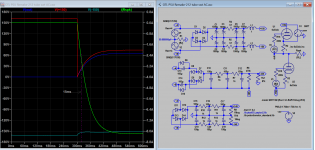
Neon 2 GDT or Mov on the output can really lower the spike (breaking point) therefore arcing is avoided, I think N2 could be reduced to 50V from 90V. Attached is sim with 39V zener back to back.
Attachments
Last edited:
I agree with you (or, at least, with what I think you are hinting at!), namely, that the mere fact that the speaker is protected from long-term DC voltages by what is effectively a series capacitor is by no means a guarantee that it won't get fried in the first fraction of a second when the capacitor is dumping its charge through the speaker. And as your plots are showing here, in the first 15 milliseconds there is little to choose between the R1=1m and the R1=1k situations, as far as the speaker is concerned.Can someone comment on how safe is 1k R33 resistor?
I remember having great fun in my youth zapping bits of wire or aluminium foil by connecting a charged capacitor across them. I have often thought with OTLs that it would be easy to imagine the speaker voice coil suffering a similar fate, even if it was supposedly protected by a series capacitor (or, almost equivalently, the TM arrangement with the R1=1k choice).
I think probably the cut-off protection idea (or perhaps crowbar type) is the better way to go. As you know, I have reservations about the idea of a mechanical relay breaking the connection to the speaker. But I agree with you that maybe a MOV protector might be able to tame the arcing problem. Or using mosfet switching. Or perhaps, using relays to short-circuit the speaker and simultaneously divert the amplifier output to a dummy load.
i built one Tim Mellow OTL and is was a hit in the audio show we entered it with....
long term realiability is a concern..
long term realiability is a concern..
Tim Mellow mentions in his article that one can increase the input impedance by grounding C1 and connecting the input to C2. However, this will, as he says, "tend to unbalance the input stage slightly unless you use an "ideal" solid-state current source in place of R7". I tested the arrangement briefly and quite superficially (with a LM317 wired as a current source - the "cold" end of the current source connected to ground not to -430V). It seemed to work - but I did not test it very thoroughly. One of the reasons I am interested in this modification is that this would make the amp non-inverting (as it is published it invents the absolute phase - which, in most cases, in not problem since the remedy is to invert the loudspeaker connections, but for aesthetic reasons...). Yet, there would be a couple of other small advantages: The neon bulb N1 would not be needed and the burden on RV2 during warm-up would also be reduced.
Has anybody experimented with this approach.....?
In any case: I am very pleased with the amp as it is ... so it is more of an academic concern
Has anybody experimented with this approach.....?
In any case: I am very pleased with the amp as it is ... so it is more of an academic concern
- Home
- Amplifiers
- Tubes / Valves
- OTL designed by Tim Mellow with 4 6C33C?