Tracking gain is an adjustment but it generally has a very wide margin on a good player and once the servo is locked then its an all or nothing thing. It either works and looks perfect on the scope or it doesn't.
Try and understand the VC point concerns 🙂
If it is a virtual ground point then it will be at some given DC voltage. If the scope has a mains ground connection via the mains lead and if the player is also mains grounded then as soon as you touch the scope probe ground lead onto VC you create a dead short via the grounds.
If the player uses a two core mains lead (so no mains ground) and you have nothing else external connected to the player then connecting a grounded scope lead to VC should be OK in principle. In that case you would only know by trying.
You test the all the DC voltage rails in the power supply by using the scope in conjunction with the DVM. The DVM shows a DC voltage and the scope (used with AC coupling) will show any noise or ripple on the rail. All stabilised rails should have essentially no noise or ripple.
hi there,i have tested the scope and find with a generator i will make a nice wave form,i thing the scope works, am i to be worried about testing the power supply on the dc side with scope? i see that one out put is 15v ,will this damage my scope? i probed at the less voltage out puts on power supply and got a fuzzy wave form,very sharp saw like,this was present on all out puts with exception of two which displayed nothing at all at the setting its on now which is .10mv ac 2us, is this to be expected??
pcbs dont look to have any bad joints,
if there is fuzzy noise coming from power supply would that be the main filter caps failing?
if there is fuzzy noise coming from power supply would that be the main filter caps failing?
for a closer look at power supply would it be possible for you to take a copy of the pcb and show me where to test and what to expect at that test site??
It sounds like this is going outside your comfort zone 🙂
Checking the power supply voltages are clean is a the first step in any fault finding. Proving them clean and correct means we can consider other things. Yur scope (the analogue one) should be safe up to at least 400 volts DC (it will say next to the BNC socket the probe connects to).
All these need to be checked. Using chassis as a ground point will introduce a little noise but it should only be a few millivolts at most. They will probably be fine but checking them really is the first step and the golden rule of fault finding. You will see ripple on unregulated rails but those are all before (in front of) the regulators.

would you like me to write the voltages down for you to look over
?
ill do that now, please give me an idea what to set scope to for this test?
?
ill do that now, please give me an idea what to set scope to for this test?
would you like me to write the voltages down for you to look over
?
ill do that now, please give me an idea what to set scope to for this test?
If they are correct then that is all that counts. A +12v rail for example should be within say 11.7 to 12.3v, and it should be steady and clean. The scope is set to AC coupling and the volts per division is turned to a very sensitive setting such as 5 millivolts per division. The AC coupling means you see a single trace in the middle of the screen and it should be noise and ripple free. You will see some noise but it should be very low, a few millivolts peak to peak.
I think the fault is probably elsewhere but checking rails really is the first and golden rule of fault finding. It should take only a minute or so to whizz through them all 🙂
hi
the only test points that have a wave is the ones marked f, there is two ,a very clean sine, voltages is close
the only test points that have a wave is the ones marked f, there is two ,a very clean sine, voltages is close
i got my scope cost me 20 dollars ,id say it needs a service but thats another job one day, some of the pots seem noisey but other than that it works
That is normal. If you look at the circuit you will see they are derived from the mains transformer and are the AC filament voltage for the vacuum fluorescent display. The F/F voltage is bias (tied to) a DC voltage.the only test points that have a wave is the ones marked f, there is two ,a very clean sine, voltages is close
All normal.
ok thats good,i did notice that those lines came tranformers , so my problem is on servo pcb? is it not that pcb that controls the mech parts?
I think you have to go back to looking at the RF signal and trying to see what if anything changes when it skips.
At the same time I would also connect a meter across the sled motor drive voltage and monitor that voltage carefully as a disc plays. If the sled sticks mechanically then the voltage across the motor will start to rise (before it skips) and then when enough voltage s present the sled jumps forward and the player skips.
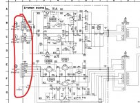
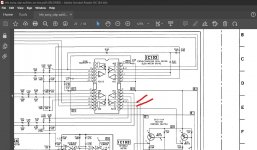
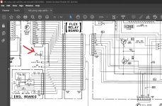
The sled drive is derived here but can be monitored at the motor. You would need to tag a couple of wires to wherever is easiest and connect the DVM up securely that way.
The meter is connected across these two points.


ok, ill do this asap, please forgive me if i seem not keen, my wife is very ill and only muck about with this stuff to take my mind off things,I think you have to go back to looking at the RF signal and trying to see what if anything changes when it skips.
At the same time I would also connect a meter across the sled motor drive voltage and monitor that voltage carefully as a disc plays. If the sled sticks mechanically then the voltage across the motor will start to rise (before it skips) and then when enough voltage s present the sled jumps forward and the player skips.
The sled drive is derived here but can be monitored at the motor. You would need to tag a couple of wires to wherever is easiest and connect the DVM up securely that way.
The meter is connected across these two points.
View attachment 1030470
View attachment 1030471
today she had a very bad turn and has to be keep in hospital, for how long i dont know, the doctor says she may not come home again, i tend to agree with him, things are looking grim for her, i dont mean to dump this on you but i dont have any one else to chat to and i dont want you to think im ungrateful for your help in taking so long to reply and to exercise the job
im not going to be able to do any thing for a day or two,
i look forward to the work as it gives me something else to concentrate on for a hr or two
thanks for all your help
mike
I'm very sorry to hear that. Of course just come back here as and when you feel able or feel you want to.
hi ,i got that little pcb out,im not sure if the diagram is looking at it component side up or down, i dont want to solder tails on the wrong points as i worry that hooking a volt meter up to the wrong points may damage some thing? do you have any ideas?
ok after some studying i have worked it out to be the two dead center on pcb,im reading at moment a steady 4.78v dc, ill wait for a skip and report findings
after a little bit of time it does move up and down from a max of 4.78v to a min of 4.69v ,however i has skipped 4 times and there is very little difference in voltage at skipping, for example the most movement at skip was from 4.78v to 4.80v but only once ,every other time it moved to 4.79v ,
i hope this means something, what is the line voltage meant to be, am i right in thinking 7v ?
i may be looking at things upside down,
it was some fiddly soldering to attach the tails on that little pcb, but it will look good once they are removed after testing complete, i ordered the 6x caps for the servo pcb in case one is dying and also when its repaired i may just change them out as its getting old in any case,
the philips i did from the 70s had every one bad ,so it will help me in the years to come im thinking, but dont worry im not fitting them till problem is found
thanks
mike
Connecting a voltmeter to anything will not cause problems. It is a very very high impedance load. Just make sure the meter is really on voltage when you connect it (and not on a current or ohms range) and its fine.
You are connecting the meter across the sled motor and the expected voltage would be very low when playing. Typically a few hundred millivolts at most as the motor literally shuffles along. So I would recheck where you measured and the result. What you are looking for is that voltage starting to increase and the sled staying put. The voltage will keep rising until the friction is overcome and the sled move forward again but that is when it can skip.
The 4 to 5 volts you mention would spin the sled motor very quickly indeed and move it from end to end in less than a second.
- Home
- Source & Line
- Digital Source
- Sony CDP-XA50ES problems