Hello All,
I have just received a TSE ll PCB from Mr. Anderson and also started ordering parts. I have yet to order transformers. Given the cost of NOS #45 tubes, I think ordering reasonably good transformers makes sense. I want to hear this amplifier at its best, but preferably without excessive cost.
Is there a discussion on transformer choices? I read some of the recommendations on the TubeLab website, but wonder if there are more recent recommendations.
I have fairly good speakers to use with the TSE ll amplifier. Most of these though may not be sufficiently efficient, if not, I still have a pair of 16 Ohm EV 12TRXBs that should be. However this may make choosing output transformers a little more complicated. I know for example that some of the Edcor output transformers can only be ordered with a single output impedance.
Thank you in advance for suggestions.

Hi Allen, its a terrific amp. I built the 2A3, 300b and two SSEs myself. If you do a search you'll find plenty of information by George and others. Here's a few.
https://www.diyaudio.com/community/...a-first-time-tube-builder.341907/post-5903424
https://www.diyaudio.com/community/threads/se-power-transformer-tube-selection.344757/post-5964672
https://www.diyaudio.com/community/threads/tubelab-simple-se-tube-selection-help.151503/post-1922431
https://www.diyaudio.com/community/threads/power-transformer-for-tubelab-simple-se.221022/
https://www.diyaudio.com/community/threads/help-with-tubelab-se-component-selection.197442/
Thank you, I'm reading through the linked threads. What a pleasant community.Hi Allen, its a terrific amp. I built the 2A3, 300b and two SSEs myself. If you do a search you'll find plenty of information by George and others. Here's a few.
https://www.diyaudio.com/community/...a-first-time-tube-builder.341907/post-5903424
https://www.diyaudio.com/community/threads/se-power-transformer-tube-selection.344757/post-5964672
https://www.diyaudio.com/community/threads/tubelab-simple-se-tube-selection-help.151503/post-1922431
https://www.diyaudio.com/community/threads/power-transformer-for-tubelab-simple-se.221022/
https://www.diyaudio.com/community/threads/help-with-tubelab-se-component-selection.197442/
I have read through the linked threads and a few more and think I have chosen suitable transformers and a choke for the TSE-ll amplifier.
Perhaps someone with more experience can say if the following are good choices, I'd appreciate knowing.
All Edcor
Power Transformer XPWR131-120
Choke CXC125-10 H 200mA
Output Transformers CXSE25-5K-25 8 Ohm
Does anyone know if the parts list can still be used to order from Digikey or Mouser?
Thank you.
I used a power trafo similar to yours and got 375 B+ with a GZ34 and 47uF cap. The 10H choke should be fine. Initially I ran the 300b with the same OPT as your - CXSE25 and it sounded fantastic. Eventually when I put everything into its chassis decided to go with the GXSE15. I run Altec speakers and didn't miss the bigger OPTs.
The Edcor XPWR-131 is spec'd for a TSE. A long ago a member here (Rknise I think) paid the NRE fee to have Edcor make the first one. This has 260V and 330V taps to run 300B's (using the 330V taps), and 45's and 2A3's (using 260V taps). Keep in mind that you'll have an extra set of HV wires that you won't be using....I kept them long and just terminated them to nowhere on a terminal strip.
Thank you sunil and boywonder, it is good to have confirmation. I'll plan to terminate the long extra wires as you suggest.The Edcor XPWR-131 is spec'd for a TSE. A long ago a member here (Rknise I think) paid the NRE fee to have Edcor make the first one. This has 260V and 330V taps to run 300B's (using the 330V taps), and 45's and 2A3's (using 260V taps). Keep in mind that you'll have an extra set of HV wires that you won't be using....I kept them long and just terminated them to nowhere on a terminal strip.
Most of the P/Ns will still be good......plug them in and have a highlighter handy to mark the obsolete stuff.Does anyone know if the parts list can still be used to order from Digikey or Mouser?
Thank you.
Very interesting reading. I have chosen Lundahl 1620 40mA output transformers for 45 tube with good results and Hammond 158M 10Henry 200 ohm for the choke. In my old TSE built. I have a question about the C2 cap. (sorry I know is is nor about transformers). I am now planning a TSE ll build and I am wondering about the C2 electrolyte capacitor. On the schematic the +for C2 goes to ground and to the - for c1, c12, c13? Can you explain this for me? Way is it connected so and way have it to be this way?
Best regards
Michael Jessen
Best regards
Michael Jessen
Hi Michael. it is all relative! There is ground at 0v, and positive and negative rails wrt ground. Since on the negative rail the ground is more positive than the rail, the positive of the cap goes to the ground, and the negative of the cap to the more negative rail.
Sorry for the slow replies......life happens.Very interesting reading. I have chosen Lundahl 1620 40mA output transformers for 45 tube with good results and Hammond 158M 10Henry 200 ohm for the choke. In my old TSE built. I have a question about the C2 cap. (sorry I know is is nor about transformers). I am now planning a TSE ll build and I am wondering about the C2 electrolyte capacitor. On the schematic the +for C2 goes to ground and to the - for c1, c12, c13? Can you explain this for me? Way is it connected so and way have it to be this way?
Best regards
Michael Jessen
The heater / filament supply in the TSE and TSE-II is a bit unusual. It needs to do two of three jobs depending on tube choices. With either choice all tubes run on DC to eliminate low level line frequency related IMD in the audio output. The driver tubes (5842 / WE417A) need 6.3 volts at 300 mA each, 600 mA total. The output tubes typically need either 2.5 volts at up to 5 Amps (2 X 2A3's) or 5 volts at about 2.5 amps. Other voltages are also possible.
In either case dual diode D1 and the individual diodes D4 and D5 make a full wave bridge rectifier with C1, C12, and C13 in series with C2 as the filter capacitor. This generates somewhere between 6 and 8 volts of DC depending on the actual voltage provided by the 6.3 volt winding on the transformer. R3 drops some voltage to provide 6.3 volts to the 5842's.
If we want 5 volts for the output tube heaters a jumper is placed from pad 3 to pad 4. This removes C2 from the circuit as it is shorted by the jumper, and does not even need to be placed in the board if 2.5 volt tubes are not used. The full wave bridge now has its negative end connected to ground and the CT on the 6.3 volt winding is not used (and must NOT be grounded). All filament supply voltages are positive and the circuit looks somewhat typical. The unregulated 6 to 8 volts is dropped by R3 and fed to the 5842's. The same voltage source feeds the regulator which produces 5 volts for the 300B's.
If we want 2.5 volts to run 45's or 2A3's we don't want to feed the regulator 8 volts on its input. If 5 amps of current is needed for 2A3's the regulator must drop up to 5.5 volts at 5 amps resulting in 27.5 watts of heat dissipation. This would require a rather large heat sink, and make for a hot amplifier, so the power supply is reconfigured. The jumper is now placed from pad 1 to pad 4. This removes the short across C2 and grounds the CT on the 6.3 volt winding, making the supply similar to the bipolar supplies seen in many solid state amps. Now we have a +/- 3 to 4 volt dual supply.
Positive 3 to 4 volts is fed to R3 from the dual diode and C1, C12, and C13. Pin 3 of the 5842's see a positive voltage of 2 to 3 volts since some is dropped across R3. The voltage regulator now gets a positive 3 to 4 volts reducing it's heat dissipation to 3 to 7 watts depending on the actual voltage delivered by the power transformer. Pin 9 of the 5842's see a negative voltage (3 to 4 volts) developed across C2 from diodes D4 and D5, hence it's positive end being grounded.
Jeg har bemærket at pin4 på udgangsrør fatningen ny TSE ll går til g (-) og pin 1 er + men på den gamle TSE er det omvendt. Er der en der kan forklare mig hvorfor det er sådan.
Hello All,
I'm off to a slow start on this project, however, progress is being made. The Edcor transformers and choke arrived a few weeks ago, and I've just submitted orders for most of the remaining parts to Mouser and Digikey. Several parts are backordered though and may not arrive for a few months, although, some of these I was able to find on Amazon and Ebay. I ordered from redundant sources on the possibility some may not be available for some time.
The tube sockets and tubes arrived from Antique Electronics and Tubedepot. I also have a plate of Aluminum on the way for the chassis. Given the backorders, slow progress may not be entirely due to procrastination.
I have one question at present. I intend to use #45 output tubes and see in note #2 of the Notes for the TSE-ll BOM that a 100 Ohm resistor is required for resistor #2. How many Watts and what tolerance is required for R2?
Same as R1, 1/4 watt 1% 100 ohm.I have one question at present. I intend to use #45 output tubes and see in note #2 of the Notes for the TSE-ll BOM that a 100 Ohm resistor is required for resistor #2. How many Watts and what tolerance is required for R2?
Jeg har et spørgsmål om radiatorspændingen på 45 rør. Pin 1 og pin 4.jeg ser at pin 4 i printkort i TSE ll går til grund (-) på diagrammet er der vist, at pin1 er (+) og pin 4 er (-) hvorfor er det således? Er det ligemeget hvilken vej radiator strømmen løber igennem røret?Jeg har bemærket at pin4 på udgangsrør fatningen ny TSE ll går til g (-) og pin 1 er + men på den gamle TSE er det omvendt. Er der en der kan forklare mig hvorfor det er sådan.
Attachments
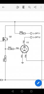
Ups jeg ser at pin1 på output fatningen ny TSE ll går til g (-) på diagram tegningen, men pin 4 på printekort går ti g (-) hvad er forklaringen? Er der en der kan forklare det?
The Eagle library part was made wrong back when the original TSE board was done. On the original TSE board, the pin numbers are wrong, the schematic is also wrong, and the two do not match. The board was electrically correct, and all the amps worked fine. When I did the TSE-II board I fixed the pin numbers on the board itself, but the pin numbers on the schematic are still incorrect. Pin 4 is grounded and pin 1 is the filament supply.
Parts are arriving from Mouser and Digikey, but several are back ordered. Particularly D1, IC 1,2&3 and Q1&2. There isn't much of a rush on assembling the amplifier, but I would like to be certain I'll eventually have the remaining parts. I have found D1 on Amazon, and the remainder of the back ordered parts on Ebay. I am not confident though that Amazon and Ebay sellers provide genuine parts, particularly when "genuine" seems overused on their websites.
Has anyone found a reliable supplier for the parts listed above? Other than Mouser and Digikey.
Has anyone found a reliable supplier for the parts listed above? Other than Mouser and Digikey.
- Home
- More Vendors...
- Tubelab
- Starting TSE ll