The temps got up within 5 - 10 minutes and then stabilized. I had it on for ~1 hour while adjusting 1 channel.

Another option for a signal generator is the sound output of a Rasperry Pi with this command:Sadly, I don’t have a signal generator; I was playing a YouTube video that was nothing but a 1KHz tone - essentially a simple check that the input jacks and R1 were sound (no pun intended). The resistors measure better than .5%.
speaker-test -t sine -f 1000
one can generate tones from about 30-8kHz, or pink noise.
Yesterday, in a fit of desperation and impatience, I started to unsolder both Q4 in order to swap channels to try to narrow things down. I got quite frustrated as I could not desolder the middle pins, even with the devices pulled away from the sinks - the Soldapullt left more solder than it sucked, and wick was useless. I ultimately succeeded by heating the pin while pulling on the tab; crude, but effective. I am still stumped at why I had so much trouble.
However, having had another long look at the underside, I noticed the negative leg of CL4 (actually CR4, as I have the RCA jacks swapped, but I digress) had very sparse solder, and the other looked ok but a bit blobbier than I like. I was sure this was the culprit - it all made sense.
Having thrown in the towel last night (option #2 was throwing the amp), This afternoon I dug out my old RS 60W iron. After giving the heat sink pins another blast (still messy!), I turned it on the the C4 pair with a bit more solder, then hooked the amp back up.
I was disappointed when I fired it up and the volume issue persists.
I must note that I had quickly measured the AC voltages across the outputs with music running during my initial trial, and the voltages were markedly lower on the L channel; I am certain that a test with a more stable, known signal would result in the same finding.
Short of swapping MOSFETs, I don’t know what else to try. I have a second board and set of matched MOSFETs that I can build up, but even if I get it working properly I won’t have learned anything.
Well, this is embarrassing.
After doing some wire swapping - which I did last night but clearly didn’t do the math correctly - it became clear that the speaker was at fault.
The speakers can be bi-wired, but have jumpers between HF & LF posts. I happened to have connected the speaker cable to the HF posts but apparently one of the jumpers wasn’t making contact and so the speaker was tweeting but not woofing.
I appreciate everyone’s input. Now I’m off to listen to some MUSIC.
After doing some wire swapping - which I did last night but clearly didn’t do the math correctly - it became clear that the speaker was at fault.
Congrats on finding the problem. Enjoy the amp!

It’s funny, the thoughts that run through my mind. Visions of ordering 75 more boards, or graveling for another batch of MOSFET’s. I was about to sh*t brick if something like that was at fault.
If 30+ people build a board and are absolutely delighted with its sound, but 1 more person builds the same board with unhappy results .. AND if the folks who actually created that board have a positive track record .. then becalm yourself. Occam's Razor deprecates the "misdesigned board" hypothesis.
@Mark Johnson
I’ve built two of the boards already, the red “experimental” board, and one production board…I know the design works. What I know nothing about is the manufacturing process and wondered if it was possible some were defective. My second fear was that I wasn’t carful enough with the transistors (as @audiosteve pointed out) and zapped some of them.
As I said, it’s funny how my mind can race to possible scenarios. You can call that whatever you like, but it's what makes me good at my job, and able to to pull off the Group Buy as well. I'm alway prepared for (most) any scenario...of either polarity and anything in between.
Last edited:
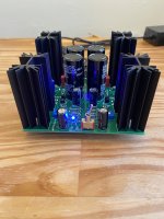
Here is mine, I finished the soldering on Friday night and turned it on on Saturday morning, but unfortunately have not biased it yet cause I only have 1 voltmeter and I don't have enough experience to only do it with one. I am hoping to borrow one tomorrow from friends.
Regardless of that, I am psyched about it. the built process was felt way easier than the ACP+, especially since ACP+ was my first soldering job ever, after that experience, I watched David from EEVblog tutorials on soldering and that helped a lot.
Kevin, Mark Johnson, and Nelson, thanks for all of the work you did to make this happen.
Daniel
Attachments
Yes, I did borrow one from a friend. I followed your video and did the biasing this morning. I think I did it right, though, my starting values were slightly different than yours, and even between right and left channels were different and threw me off for a bit but by the end of it, I think got them to stay really close to 300 mV.Nice work Daniel! Any luck on locating a second meter?
Everything sounds good. I don't have any issues with it so far, I left it running most of the afternoon. I am thinking of indulging my OCD personality and check the biasing tomorrow and see if it has varied significantly from today.
Thanks
Daniel
One reason could be, that you didn't use a green connector for the left input!Yes, I did borrow one from a friend. I followed your video and did the biasing this morning. I think I did it right, though, my starting values were slightly different than yours, and even between right and left channels were different and threw me off for a bit but by the end of it, I think got them to stay really close to 300 mV.
Everything sounds good. I don't have any issues with it so far, I left it running most of the afternoon. I am thinking of indulging my OCD personality and check the biasing tomorrow and see if it has varied significantly from today.
Thanks
Daniel
1 voltmeter is adequate. You just rotate through the measurements, adjusting in small increments. You have to do it this way anyway, but multiple meters is more convenient.

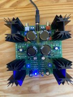
One reason could be, that you didn't use a green connector for the left input!

BTW, I did feel bad not getting the green ones, but it was too late, maybe next time I need to order parts, I'll through a pair of green connectors in the cart.One reason could be, that you didn't use a green connector for the left input!
I just finished mine. Sounds great! It has 'space' and detail compared to the little class D it replaced. It took longer than I expected to get the bias set.
It's my new desktop amp driving a pair of Markaudio CHR-70s from via Grace design SDAC. Not too shabby.
It's my new desktop amp driving a pair of Markaudio CHR-70s from via Grace design SDAC. Not too shabby.
Last edited:
If you want a good laugh...here's a video of me biasing the amp with one meter. I didn't want the video to be an hour long so I was moving too quickly. The key to doing this well would be to make "small increments". It's definitely possible with one meter and if you're new to this give yourself a good hour...it's not a race.1 voltmeter is adequate. You just rotate through the measurements, adjusting in small increments. You have to do it this way anyway, but multiple meters is more convenient.
ONE METER BIASING ACA MINI
Last edited:
- Home
- Amplifiers
- Pass Labs
- DIY ACA mini